Pressure detection device

a detection device and pressure technology, applied in the direction of rapid change measurement, fluid pressure measurement using elastically deformable gauges, instruments, etc., can solve the problems of linearity damage, linearity damage in the spring characteristics of the pressure receiving diaphragm b>215/b>, etc., to improve the sensing

Active Publication Date: 2006-05-04
DENSO CORP
View PDF6 Cites 47 Cited by
  • Summary
  • Abstract
  • Description
  • Claims
  • Application Information

AI Technical Summary

Benefits of technology

[0030] In view of the above-described problems, it is an object of the present invention to provide a pressure detection device which improves sensing characteristics.

Problems solved by technology

However, when the pressure receiving diaphragm 215 has the function of receiving pressure, the function of holding a pre-load, the function of absorbing fluctuations in the pre-load caused by the difference in thermal expansion, and the function of transmitting the pressure, and further is exposed directly to a measurement environment, there are presented the following problems.
Moreover, there is a possibility that a temperature change caused by thermal shock or the like will cause damage to linearity in the spring characteristic of the pressure receiving diaphragm 215 at the time of low temperatures or high temperatures.
Various problems such as a problem that linearity in the spring characteristics of the pressure receiving diaphragm 215 is damaged are raised by heating, the adhesion of the deposits, and the excessive application of load.

Method used


Image

  • Pressure detection device
  • Pressure detection device
  • Pressure detection device

Examples


first embodiment

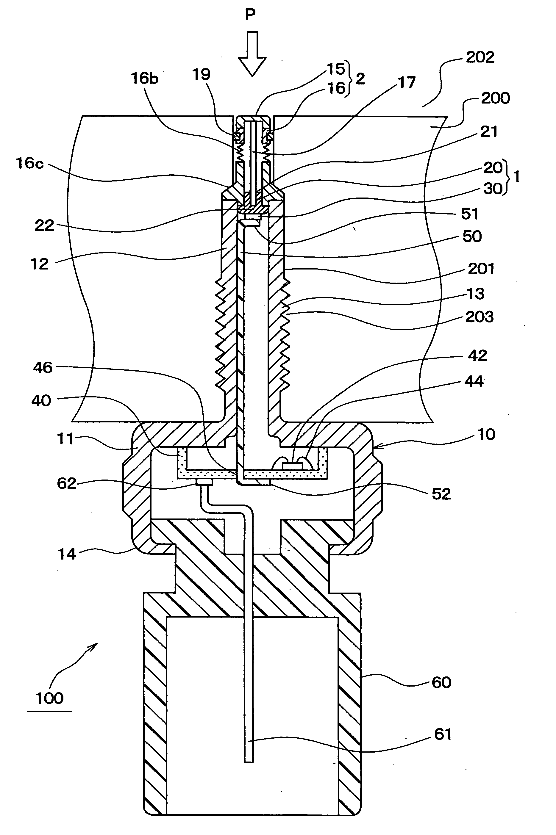
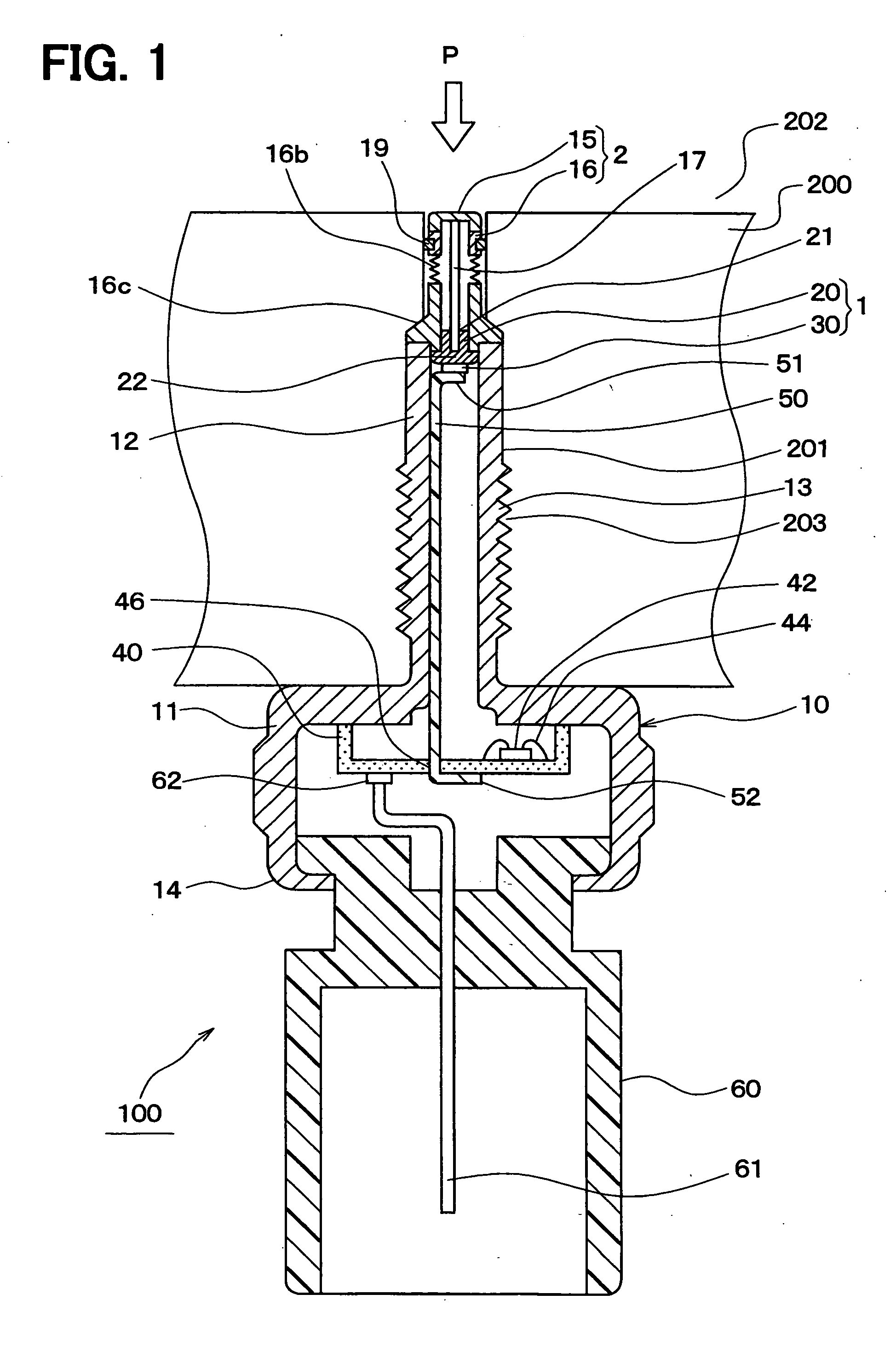
[0059] In this embodiment, a pressure detection device 100 is typically used as a combustion pressure sensor.

[0060] As shown in FIG. 1, in the pressure detection device 100 as a combustion pressure sensor, a pipe portion 12 of a housing 10 is inserted into a threaded hole portion 201 formed in an engine block 200 of an automobile and is jointed thereto by screwing, and senses pressure (cylinder pressure) in a combustion chamber 202 as a detection pressure.

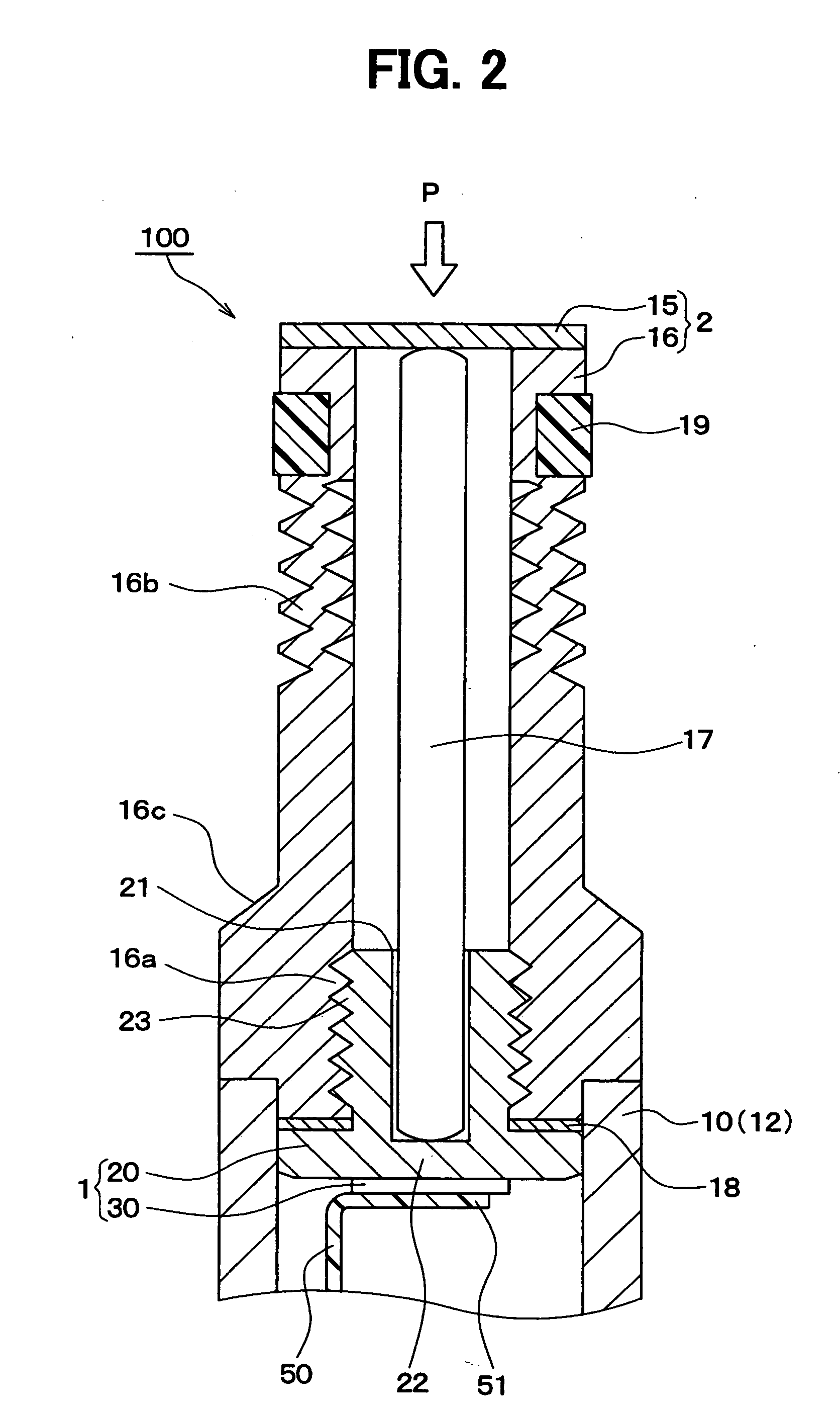
[0061] The housing 10 of the pressure detection device 100 of the present embodiment is constructed of a cylindrical main portion 11 and the slender cylindrical pipe portion 12 which is more slender than the main portion 11.

[0062] These main portion 11 and pipe portion 12 are made of metal, for example, stainless steel by cutting or cold forging. In the present embodiment, the pipe portion 12 is formed in the shape of a cylindrical pipe, but may be formed in the shape of a square pipe.

[0063] In the housing 10, the main portion ...

second embodiment

[0148] As shown in FIG. 4, a pressure detection device 110 of the present embodiment includes the first part 1 having the detection element 30 as a sensing part, the second part 2 having the pressure receiving diaphragm 15, and the pressure transmission part 17. The first part 1 and the second part 2 are connected to each other, such that the pressure transmission part 17 is interposed between the detection element 30 and the pressure receiving diaphragm 15, and the pressure receiving diaphragm 15 applies a pre-load to the detection element 30 via the pressure transmission part 17.

[0149] In the above-described first embodiment, the first part 1 is constructed of two parts of the detection element 30 and the metal stem 20. However, in the second embodiment, as shown in FIG. 4, the first part 1 is constructed of three parts of the detection element 30, the metal stem 20, and an attachment part 24.

[0150] The metal stem 20, as in the above-described first embodiment, is a hollow cylin...

third embodiment

[0184]FIG. 7 shows a pressure detection device 120 of the third embodiment.

[0185] The pressure detection device 120 of the present embodiment is a modification of the pressure detection device of the above-described second embodiment. Specifically, the pressure detection device 120 of the present embodiment is mainly different from the second embodiment in that the installation position of the spring part 70 is changed.

[0186] As shown in FIG. 7, similarly to the pressure detection device 100, 110 in the above-described first embodiment and second embodiment, the pressure detection device 120 of the present embodiment also includes the first part 1 having the detection element 30 as the sensing part, the second part 2 having the pressure receiving diaphragm 15. Further, the pressure transmission part 17 interposed between the detection element 30 and the pressure receiving diaphragm 15, and the first part 1 is coupled to the second part 2 in a state where the pressure receiving dia...


PUM

PropertyMeasurementUnit
pressureaaaaaaaaaa
elastic forceaaaaaaaaaa
cylindrical shapeaaaaaaaaaa

Abstract

A pressure detection device includes a sensing part that outputs an electrical signal responsive to an applied pressure, a pressure receiving diaphragm that receives a pressure from a subject device, a cylindrical stem having a first end connected to the sensing part and a second end connected to the pressure receiving diaphragm, and a pressure transmission member located within the cylindrical member to transmit the pressure received by the pressure receiving diaphragm to the sensing part. In the pressure detection device, a side wall portion of the cylindrical stem has a spring portion which is provided to generate an elastic force in an axial direction of the cylindrical member. Accordingly, fluctuations in a spring characteristic acting on a pressure transmission mechanism of the pressure detection device can be effectively restricted by the spring portion.

Description

CROSS REFERENCE TO RELATED APPLICATION [0001] This application is based on Japanese Patent Applications No. 2004-313971 filed on Oct. 28, 2004, and No. 2005-65383 filed on Mar. 9, 2005, the contents of which are incorporated herein by reference in its entirety. FIELD OF THE INVENTION [0002] The present invention relates to a pressure detection device in which a pressure transmission part is inserted between a pressure receiving diaphragm and a sensing part to bring the pressure transmission part into contact with the pressure receiving diaphragm and the pressure sensing part in a state where a pre-load is applied to them to construct a pressure transmission mechanism. In the pressure detection device, the pressure received by the pressure receiving diaphragm is transmitted to the sensing part via the pressure transmission part to thereby detect the pressure. BACKGROUND OF THE INVENTION [0003] As general pressure detection devices of this kind, there have been conventionally proposed...

Claims


Application Information

Patent Timeline
Patent Type & Authority Applications(United States)
IPC IPC(8): G01L7/08
CPCG01L9/006G01L23/18
Inventor ODA, TERUO
Owner DENSO CORP
Why Eureka
Try Eureka