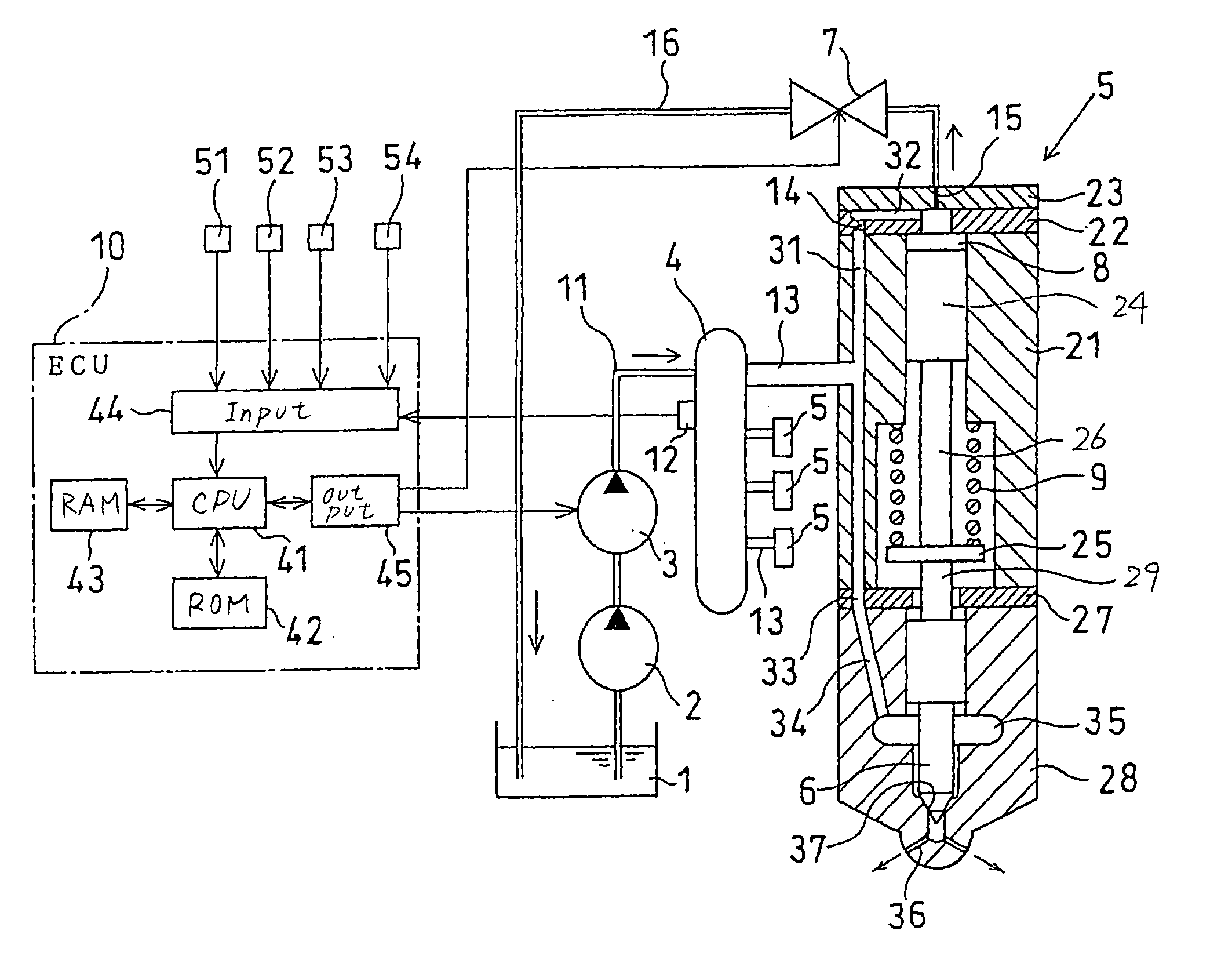
[0012] According to one aspect of the invention, there is provided an accumulator fuel injection system for an
internal combustion engine which may be installed in automotive vehicles. The accumulator fuel injections system comprises: (a) a
common rail working to accumulate fuel at a given pressure; (b) an injector which injects the fuel supplied from the common rail to an
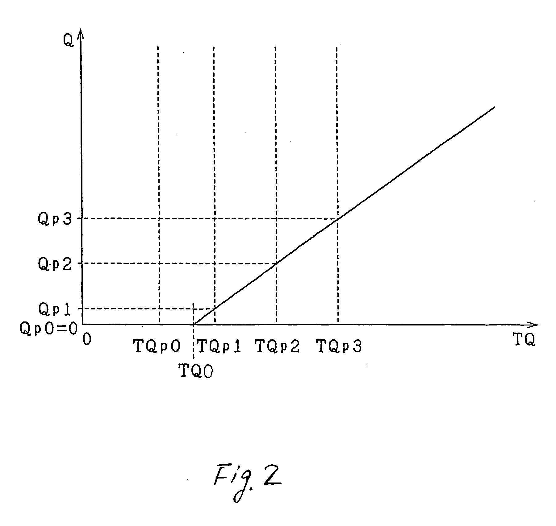
internal combustion engine; and (c) an injector controller working to output an injection pulse signal to actuate the injector. The injector controller determines a required injection quantity as a function of a given operating condition of the engine to define an effective injection pulse width and adds the effective injection pulse width to an ineffective injection pulse width to determine an injection pulse width that is a width of the injection pulse signal. The effective injection pulse width defines a duration for which the injector actually injects the fuel into the engine. The ineffective injection pulse width is given as a function of a
time lag in operation of the injector. The injector controller is designed to perform (a) an injection pulse width changing function to change the injection pulse width from a smaller value at which the injector is insensitive to the injection pulse signal to produce no spray of the fuel to a greater value at which the injector is sensitive to the injection pulse signal to spray the fuel actually, (b) a
pressure amplitude measuring function to measure an amplitude of pulsations of pressure of the fuel within the common rail a given period of time after the injection pulse signal, as changed in the injection pulse width by the injection pulse width changing function, is outputted to the injector, and (c) an ineffective injection pulse width determining function to determine the ineffective injection pulse width based on the injection pulse width, as having been changed by the injection pulse width changing function and outputted to the injector when the amplitude measured by the
pressure amplitude measuring function has exceeded a preselected level. This eliminates an error in quantity of the fuel injected into the engine arising from the individual variability and aging of the injector.
[0016] According to the second aspect of the invention, there is provided an accumulator fuel injection system for an internal
combustion engine which comprises: (a) a common rail working to accumulate fuel at a given pressure; (b) an injector which injects the fuel supplied from the common rail to an internal
combustion engine; and (c) an injector controller working to output an injection pulse signal to actuate the injector. The injector controller determines a required injection quantity as a function of a given operating condition of the engine to define an effective injection pulse width and adds the effective injection pulse width to an ineffective injection pulse width to determine an injection pulse width that is a width of the injection pulse signal. The effective injection pulse width defines a duration for which the injector actually injects the fuel into the engine. The ineffective injection pulse width is given as a function of a
time lag in operation of the injector. The injector controller is designed to perform (a) an injection pulse width changing function to change the injection pulse width from a greater value at which the injector is sensitive to the injection pulse signal to spray the fuel actually to a smaller value at which the injector is insensitive to the injection pulse signal to produce no spray of the fuel, (b) a
pressure amplitude measuring function to measure an amplitude of pulsations of pressure of the fuel within the common rail a given period of time after the injection pulse signal, as changed in the injection pulse width by the injection pulse width changing function, is outputted to the injector, and (c) an ineffective injection pulse width determining function to determine, as the ineffective injection pulse width, the injection pulse width, as having been changed by the injection pulse width changing function and outputted to the injector, when the amplitude measured by the pressure amplitude measuring function has dropped below a preselected level. This eliminates an error in quantity of the fuel injected into the engine arising from the individual variability and aging of the injector.
[0020] According to the third aspect of the invention, there is provided an accumulator fuel injection system for an internal combustion engine which comprises: (a) a common rail working to accumulate fuel at a given pressure; (b) an injector which injects the fuel supplied from the common rail to an internal combustion engine; and (c) an injector controller working to output injection pulse signals to actuate the injector. The injector controller determines a required injection quantity as a function of a given operating condition of the engine to define an effective injection pulse width and adds the effective injection pulse width to an ineffective injection pulse width to determine an injection pulse width that is a width of each of the injection pulse signals. The effective injection pulse width defines a duration for which the injector actually injects the fuel into the engine. The ineffective injection pulse width is given as a function of a
time lag in operation of the injector. The injector controller is designed to perform (a) a multi-injection function in each operation cycle of a cylinder of the engine to perform a multi-injection mode in which a main injection of the fuel into the engine is made and a pre-injection of fuel into the engine is made before the main injection and to output one of the injection pulse signals as a main injection pulse signal to the injector to initiate the main injection and one of the injection pulse signals as a pre-injection pulse signal to the injector to initiate the pre-injection, (b) an injection pulse width setting function to set a main injection pulse width that is a width of the main injection pulse signal to a value causing the engine to produce torque required to maintain running of the engine, (c) an injection pulse width changing function to change a pre-injection pulse width that is a width of the pre-injection pulse signal from a smaller value at which the injector is insensitive to the pre-injection pulse signal to produce no spray of the fuel to a greater value at which the injector is sensitive to the pre-injection pulse signal to spray the fuel actually, (d) an engine operation variation measuring function to measure a preselected engine operation variation within a given period of time after the pre-injection pulse signal, as changed in the pre-injection pulse width by the injection pulse width changing function, is outputted to the injector, and (e) an ineffective injection pulse width determining function to determine the ineffective injection pulse width based on the pre-injection pulse width, as having been changed by the injection pulse width changing function and outputted to the injector when the engine operation variation, as measured by the engine operation variation measuring function, has reached a preselected value. This eliminates an error in quantity of the fuel injected into the engine arising from the individual variability and aging of the injector.
[0024] According to the fourth aspect of the invention, there is provided an accumulator fuel injection system for an internal combustion engine which comprises: (a) a common rail working to accumulate fuel at a given pressure; (b) an injector which injects the fuel supplied from the common rail to an internal combustion engine; and (c) an injector controller working to output injection pulse signals to actuate the injector. The injector controller determines a required injection quantity as a function of a given operating condition of the engine to define an effective injection pulse width and adds the effective injection pulse width to an ineffective injection pulse width to determine an injection pulse width that is a width of each of the injection pulse signals. The effective injection pulse width defines a duration for which the injector actually injects the fuel into the engine. The ineffective injection pulse width is given as a function of a time
lag in operation of the injector. The injector controller is designed to perform (a) a multi-injection function in each operation cycle of a cylinder of the engine to perform a multi-injection mode in which a main injection of the fuel into the engine is made and a pre-injection of fuel into the engine is made before the main injection and to output one of the injection pulse signals as a main injection pulse signal to the injector to initiate the main injection and one of the injection pulse signals as a pre-injection pulse signal to the injector to initiate the pre-injection, (b) an injection pulse width setting function to set a main injection pulse width that is a width of the main injection pulse signal to a value causing the engine to produce torque required to maintain running of the engine, (c) an injection pulse width changing function to change a pre-injection pulse width that is a width of the pre-injection pulse signal from a greater value at which the injector is sensitive to the pre-injection pulse signal to spray the fuel actually to a smaller value at which the injector is insensitive to the pre-injection pulse signal to produce no spray of the fuel, (d) an engine operation variation measuring function to measure a preselected engine operation variation within a given period of time after the pre-injection pulse signal, as changed in the pre-injection pulse width by the injection pulse width changing function, is outputted to the injector, and (e) an ineffective injection pulse width determining function to determine the ineffective injection pulse width based on the pre-injection pulse width, as having been changed by the injection pulse width changing function and outputted to the injector when the engine operation variation, as measured by the engine operation variation measuring function, has reached a preselected value. This eliminates an error in quantity of the fuel injected into the engine arising from the individual variability and aging of the injector.


