Method and Control Device for Metering Fuel To Combustion Chambers of an Internal Combustion Engine

a technology of internal combustion engine and combustion chamber, which is applied in the direction of electrical control, process and machine control, instruments, etc., can solve the problems of ineffective correction and value 0%, and achieve the effect of simple mass production in large piece numbers

Inactive Publication Date: 2009-08-27
ROBERT BOSCH GMBH
View PDF1 Cites 6 Cited by
  • Summary
  • Abstract
  • Description
  • Claims
  • Application Information

AI Technical Summary

Benefits of technology

[0023]Because of this embodiment, the correlation of quantity errors in preinjections and additional injections does not have to take place individually for each manufactured injector, ...

Problems solved by technology

Thus, beginning at a certain value, the...

Method used


Image

  • Method and Control Device for Metering Fuel To Combustion Chambers of an Internal Combustion Engine
  • Method and Control Device for Metering Fuel To Combustion Chambers of an Internal Combustion Engine
  • Method and Control Device for Metering Fuel To Combustion Chambers of an Internal Combustion Engine

Examples


Embodiment Construction

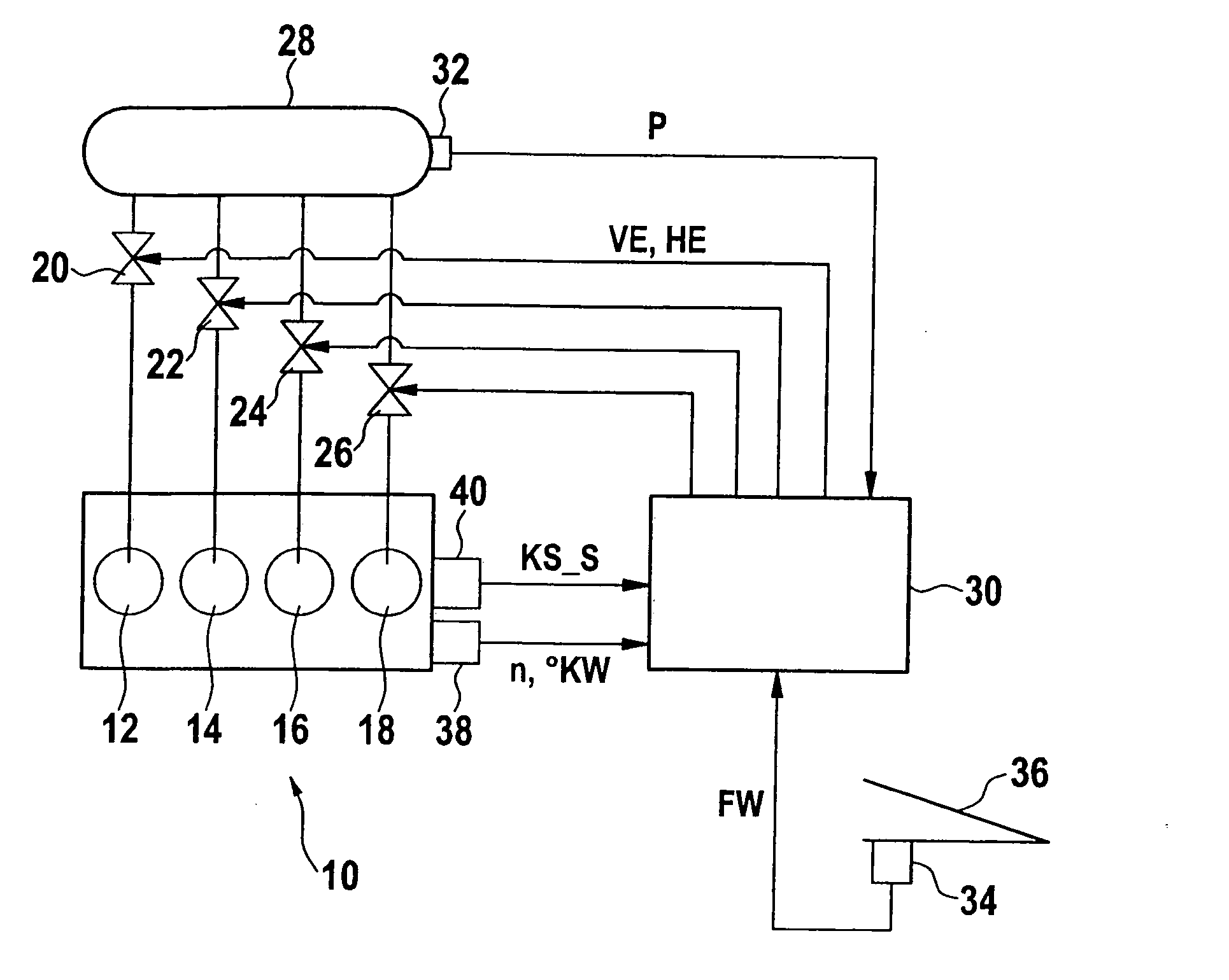
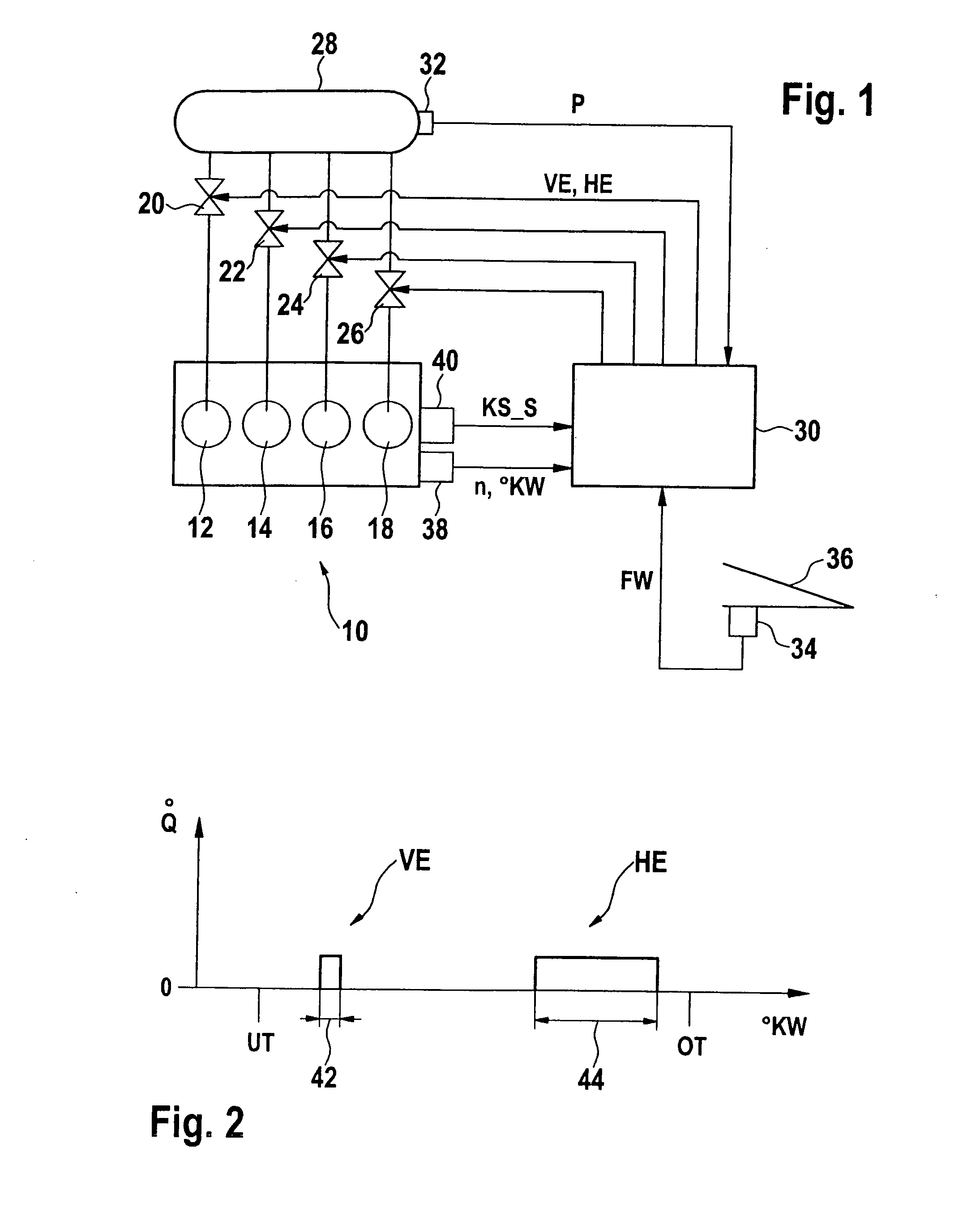
[0034]FIG. 1 shows in detail an internal combustion engine 10 having combustion chambers 12, 14, 16, 18 into which fuel from a fuel pressure accumulator 28 is metered by injections, via assigned injectors 20, 22, 24, 26. To do this, the injection valves or injectors 20, 22, 24, 26 are activated while opening by a control device 30 having individual injector pulse widths. In this context, in each case for a combustion process in a combustion chamber 12, 14, 16, 18 a comparatively small fuel quantity is metered by a preinjection VE, while a comparatively large fuel quantity is metered later by a main injection HE. A fuel quantity metered at a certain injection pulse width via an injector 20, 22, 24, 26 is a function of the fuel pressure in fuel pressure accumulator 28. In order to take into consideration this influence, a pressure sensor 32 measures this fuel pressure p and passes a corresponding electrical signal to control device 30. The overall fuel quantity, which is to be metered...


PUM


Abstract

A method for metering fuel into a combustion chamber of an internal combustion engine is provided, in which a fuel quantity to be metered for a combustion is metered by a preinjection and at least one additional injection, and in which, in the operation of the internal combustion engine, quantity errors of the preinjection are ascertained from the signal of at least structure-borne noise sensor. The method is distinguished in that a correction value is formed as a function of the quantity error of the preinjection, and at least one of the additional injections is corrected using the correction value. A control device is also provided that controls the method.

Description

FIELD OF THE INVENTION[0001]The present invention relates to a method for metering fuel into a combustion chamber of an internal combustion engine, in which a fuel quantity to be metered for a combustion is metered by a preinjection and at least one additional injection, and in which, in the operation of the internal combustion engine, quantity errors in the preinjection are ascertained from the signal of at least one sensor. The preinjection and the additional injections, especially the main injection, are also designated as being partial injections.[0002]Furthermore, the present invention relates to a control device of an injection system of an internal combustion engine having at least one injector, which meters a fuel quantity for a combustion process by a preinjection and at least one additional injection into a combustion chamber of the internal combustion engine, the control device ascertaining fuel errors in the preinjection from the signal of at least one sensor, in the ope...

Claims


Application Information

Patent Timeline
IPC IPC(8): F02B3/00F02D41/30
CPCF02D41/2451F02D41/403Y02T10/44F02D2200/0602F02D2200/025Y02T10/40
Inventor MATTES, PATRICKDAMSON, MARKSCHUELER, MATTHIASMADER, CHRISTIANKESSLER, MICHAELDAUTEL, VINCENT
Owner ROBERT BOSCH GMBH
Why Eureka
Try Eureka