

Pneumatic tire
- Summary
- Abstract
- Description
- Claims
- Application Information
AI Technical Summary
Benefits of technology
Problems solved by technology
Method used
Image

Examples
examples
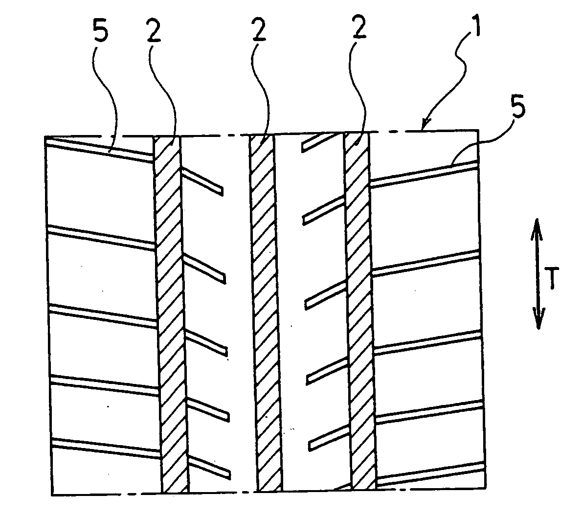
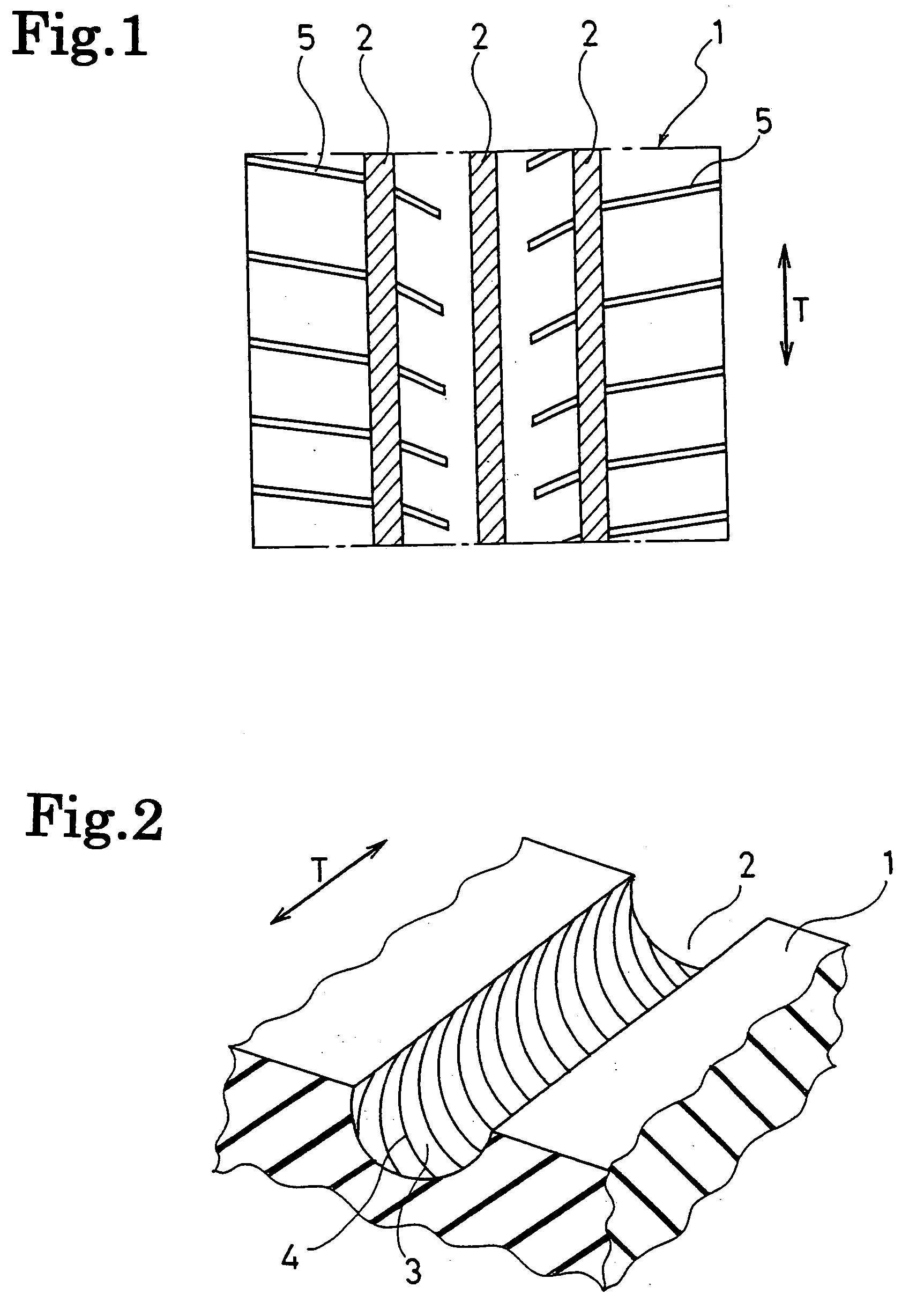
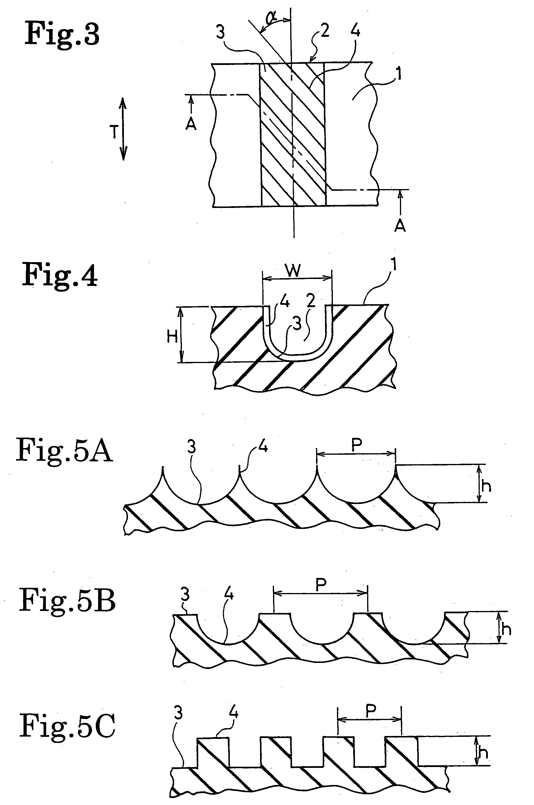
[0024] The pneumatic tires (Examples 1 to 5) of the present invention were fabricated as follows. In pneumatic tires (size: 205 / 60R15) each having the block pattern of FIG. 1, the line portions were provided in the wall face of the grooves extending in the tire circumferential direction, and the inclined angle a, height h, pitch interval P thereof were varied as shown in Table 1. For comparison, a conventional tire (Conventional Example) which was not provided with the line portions in the wall face of the grooves extending in the tire circumferential direction was fabricated. The grooves provided with the line portions had a groove width of 10 mm and a groove depth of 8 mm.
[0025] Each of these test tires was mounted on a domestically-produced car of 2.0 litter displacement and subjected to a hydroplaning test in straight running. In this hydroplaning test in straight running, the car was driven on a straight road provided with a pool having a water depth of 10 mm. The speed at whi...
PUM
 Abstract
Description
Claims
Application Information