Rope light arrangement for lamps and pedestals and packaging therefore

a technology for lamps and pedestals and rope lights, which is applied in the direction of lighting support devices, light source combinations, and with built-in power, etc. it can solve the problems of high storage cost to the retailer, high shipping and handling costs to the manufacturer, and inadequacies of conventional packaging methods for floor lamps. to achieve the effect of preventing kinking of the rope ligh

Inactive Publication Date: 2006-05-04
ADESSO
View PDF12 Cites 7 Cited by
  • Summary
  • Abstract
  • Description
  • Claims
  • Application Information

AI Technical Summary

Benefits of technology

[0007] According to another aspect of the present invention, a floor lamp package is provided including a pre-form having one or more cavities sized to seat at least two lamp pole segments and a portion of a rope light extending from within and between the at least two lamp pole segments such that a minimum arc radius of the rope light is sufficiently large to prevent kinking in the rope light. A package surrounds the preform and the floor lamp package encloses a disassembled floor lamp including at least two lamp pole segments each having an axial channel therethrough and a rope light disposed within the axial channel and extending from at least one end of each of the lamp pole segments.

Problems solved by technology

This height, together with the bulkiness of a lamp shade and a base require a bulky container for packaging the lamp and results in a high shipping and handling cost from the manufacturer to the retailer and in a high storage cost to the retailer.
Conventional packaging methods are not appropriate for floor lamps that include an internal rope light because they do not take into account the differences in the stiffness and kink potential between a power cord and a rope light.
Such damage occurs, for example, from arcing the rope light between two disassembled support poles.
The poles cannot be packaged close together or else the rope light core will arc past an acceptable arc length and can be damaged.
Secondly, once assembled, the rope light which typically has slack between pole segments to permit packaging in pieces results in free movements arrangements of the rope light within the support pole.
This can result in a jumbled, unattractive appearance.

Method used


Image

  • Rope light arrangement for lamps and pedestals and packaging therefore
  • Rope light arrangement for lamps and pedestals and packaging therefore
  • Rope light arrangement for lamps and pedestals and packaging therefore

Examples


second embodiment

[0033] Referring to FIGS. 7 and 8, in accordance with the present invention a ring shaped gasket 70 is fixedly attached to the inner diameter of coupler 42 for maintaining a tension in the rope light when lamp 25 is in an assembled state, thereby impeding the free movement of rope light R within main body 30. Ring shaped gasket 70 is preferably composed of a flexible material, i.e., rubber, and has a central orifice for frictionally receiving rope light R therethrough. The inner orifice of Gasket 70 may be circular having a diameter essentially equal to the outer diameter of sheath 200. Accordingly, gasket 70 contacts sheath 200 of rope light R impeding its free movement within main body 30 and providing tautness in the rope light which gives the rope light an appearance of lineararity and centeredness within main body 30. As opposed to a radially constant inner orifice, Gasket 70 can be provided with tabs or fingers 72 of varying sizes and dimensions. According to such an arrangeme...

third embodiment

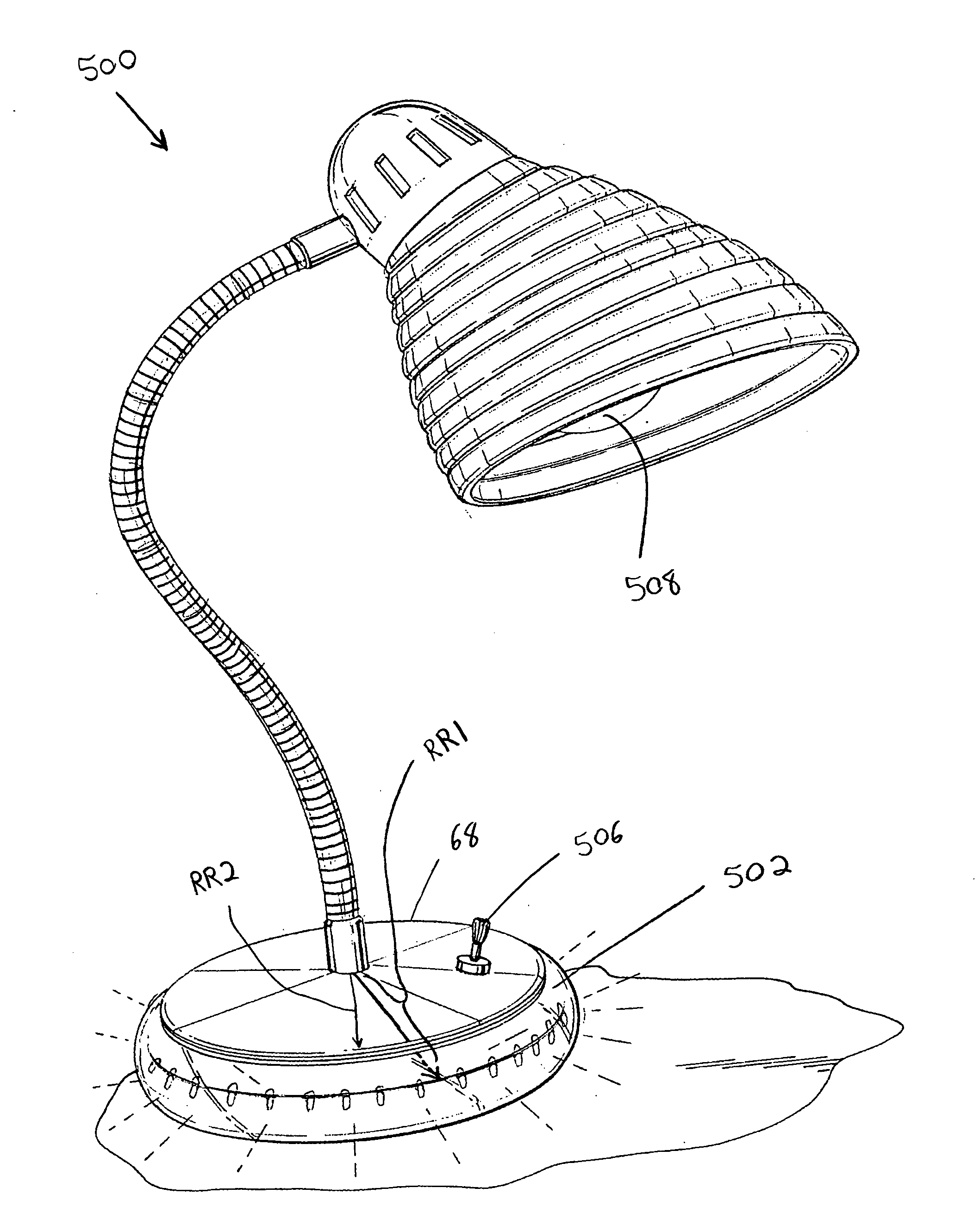
[0037] Referring to FIG. 10, the present invention is shown wherein a base 68 for supporting a lamp assembly 500 includes a circumferential exposed rope light 502 circumscribed about the outer peripheral of the base 68. Rope light 502 is preferably constructed as described above with respect to rope light R, however, as opposed to being placed within a support column extending from the base of a lamp, rope light 502 is positioned to rap around the outer surface of the base 68. Rope light 502 is disposed about an outer perimeter of the base 68 such that an arc radius RR1 of the rope light is greater than a radius RR2 to the outer perimeter of the base from which the rope light encircles. Both the arc radius RR1 and the radial distance RR2 are taken from a common point about the base 68, such as a center point. This rope light arrangement may be used in combination with lamp 25 (FIG. 1) or with any conventional lamp including a base for support. The support body thus can be a tube suc...


PUM


Abstract

The present invention relates to arrangements of rope lights in lamps and pedestals, and packaging therefor. The lamp assembly includes an upper assembly for receiving a light bulb and a lamp shade, a base and at least one coupler having a through hole. A lower support body having a bottom opening and a top opening is located between the coupler and the base and an upper support body having a bottom opening and a top opening is located between the upper assembly and the coupler. Both the upper and lower bodies each having a conduit for receiving a rope light which is disposed within the upper and lower support bodies and extends therebetween within the through hole of the at least one coupler. A first connector is adapted to connect the upper assembly to the top opening of upper body and a second connector adapted to connect the base to the bottom opening of the lower body.

Description

FIELD OF THE INVENTION [0001] The present invention relates to arrangements of rope lights in lamps and pedestals, and packaging therefor. BACKGROUND OF THE INVENTION [0002] Typically, a floor lamp must have a height sufficient to elevate a bulb in order to be effective in lighting a room. This height, together with the bulkiness of a lamp shade and a base require a bulky container for packaging the lamp and results in a high shipping and handling cost from the manufacturer to the retailer and in a high storage cost to the retailer. These costs of the product are ultimately passed onto the consumer. One prior art method for reducing the bulkiness of floor lamp packages has been to provide a floor lamp which is packaged in a disassembled state and which can be assembled by the consumer. By making the composite floor lamp package more compact, there is a savings in the shipping and handling cost. Prior art packaging methods for floor lamps include partitioning the lamp into sections a...

Claims


Application Information

Patent Timeline
Patent Type & Authority Applications(United States)
IPC IPC(8): F21V1/00
CPCA47B2220/0077F21S4/003F21S6/001F21S6/003F21S6/007F21V17/007F21V33/0012F21Y2113/00F21S4/20
Inventor SCHAAK, LEEFU, JEFF
Owner ADESSO
Why Eureka
Try Eureka