High brightness light emitting diode light source

Inactive Publication Date: 2006-05-04
GOLDENEYE
View PDF31 Cites 128 Cited by
  • Summary
  • Abstract
  • Description
  • Claims
  • Application Information

AI Technical Summary

Benefits of technology

[0016] In another embodiment of this invention, multiples of LEDs and heat pipes are arranged to form a cubical, rectangular, pyramidal or tapered light recycling cavity that has an output aperture. Multiple LEDs are arranged within a light recycling cavity such that a high percentage of the interior of the cavity is covered with LEDs. If the area of

Problems solved by technology

However, very few electrically isolating bonding materials are ava

Method used


Image

  • High brightness light emitting diode light source
  • High brightness light emitting diode light source
  • High brightness light emitting diode light source

Examples


Embodiment Construction

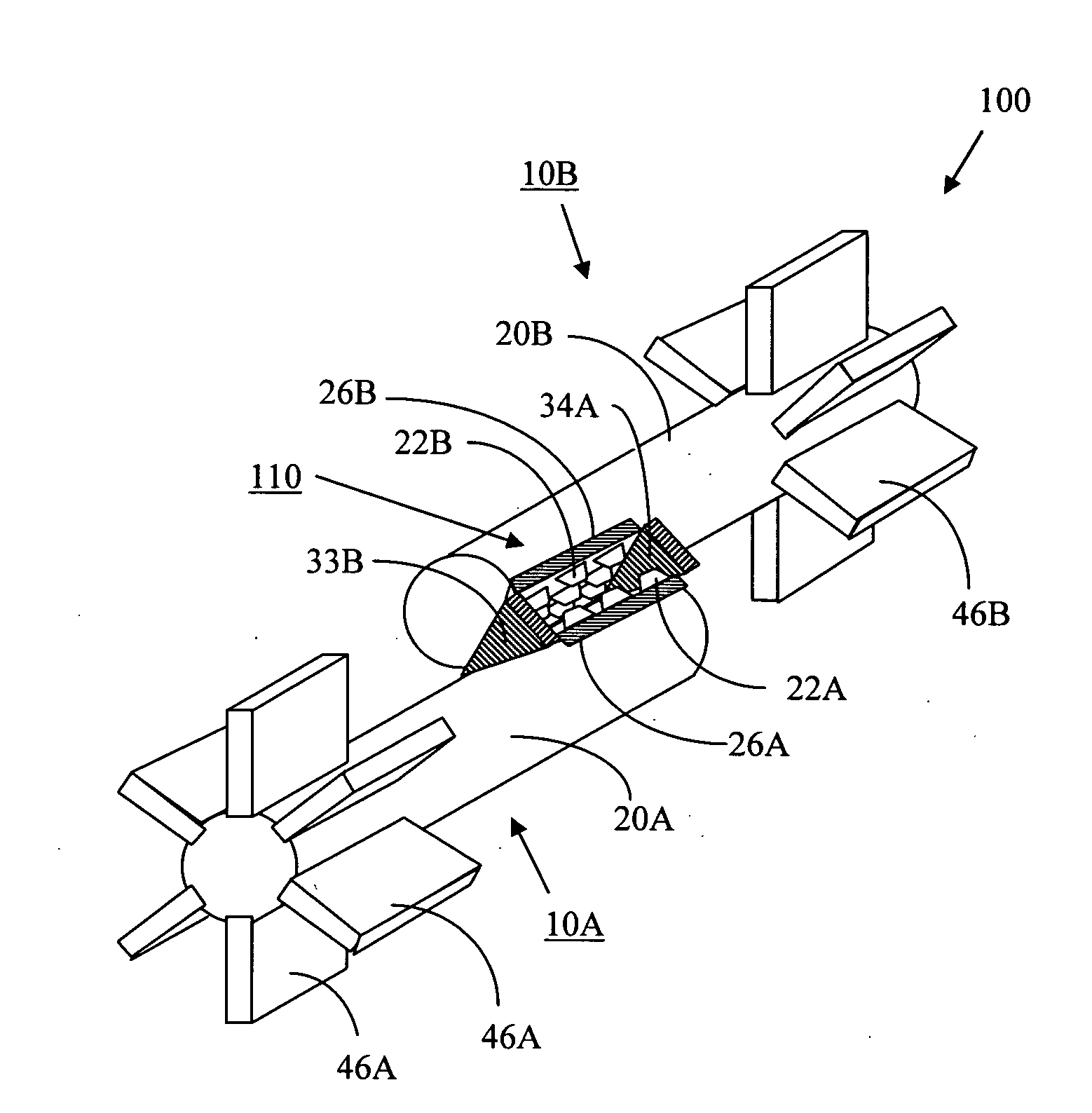
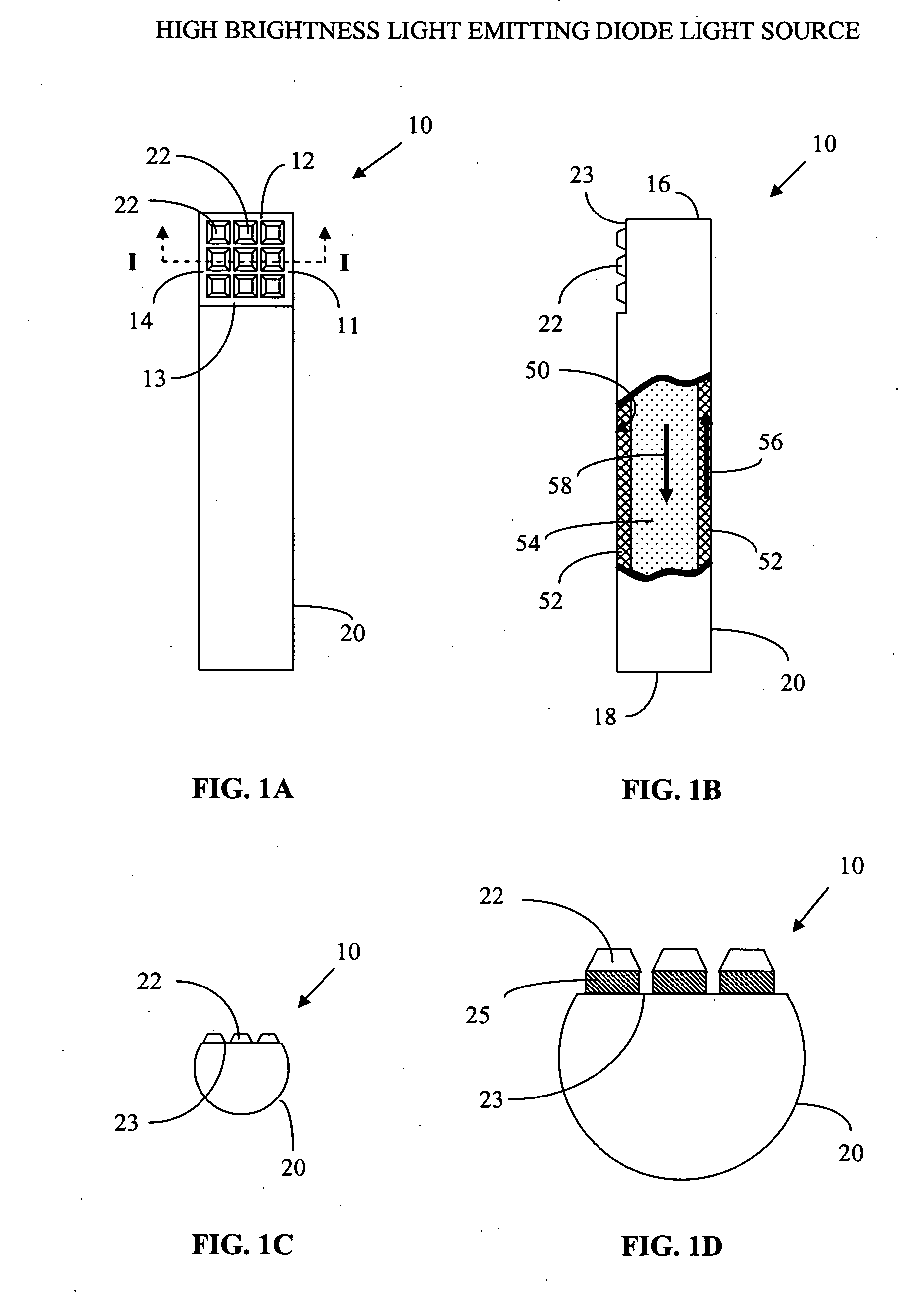
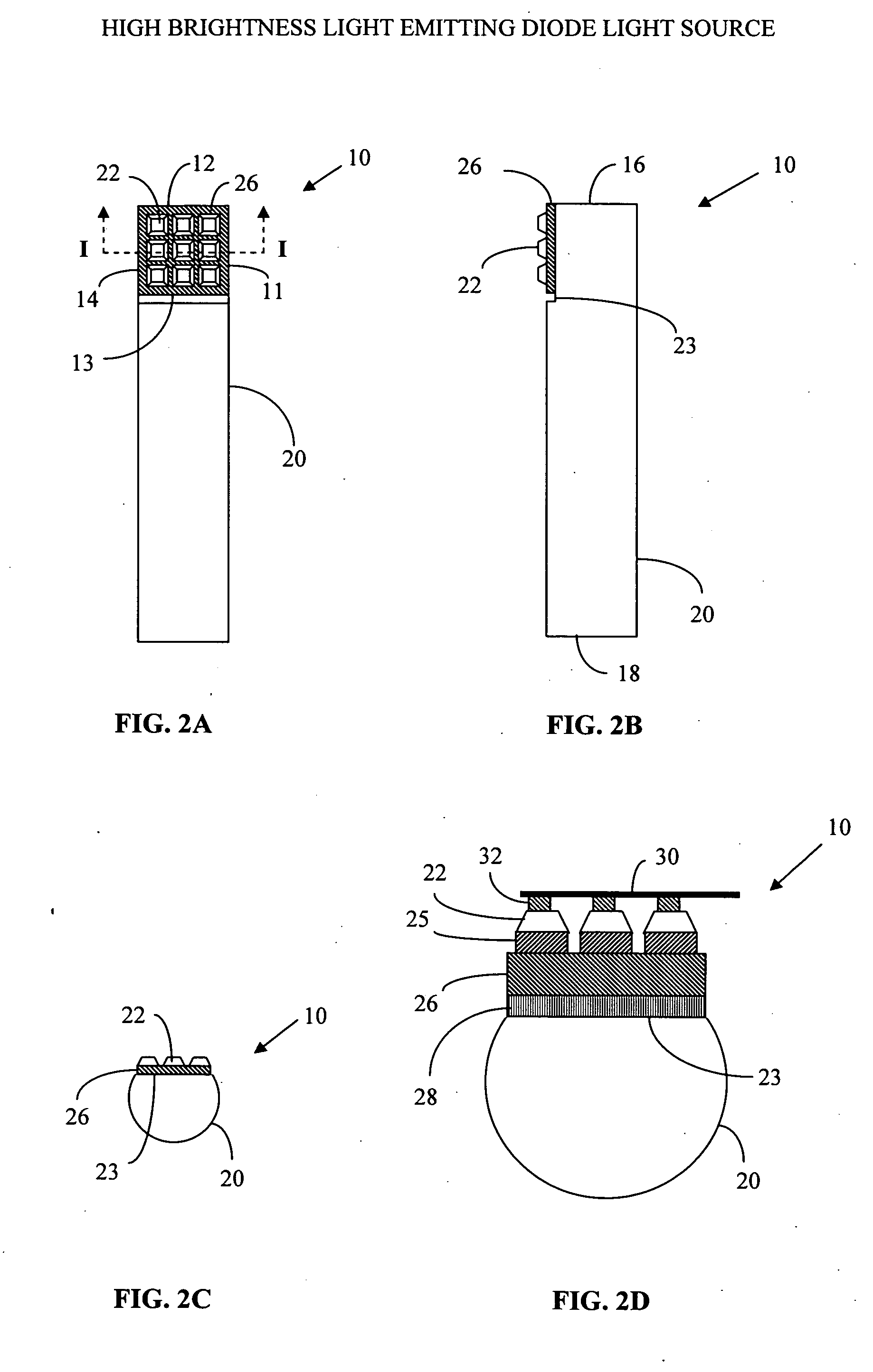
[0027] The invention consists of one or more high brightness LEDs bonded to a heat pipe, a liquid based cooling device or a thermal conducting means. Multiple heat pipes can be arranged such that the corresponding multiple LEDs form a light recycling cavity for enhancing the output luminance of the LEDs.

[0028] LEDs can be highly reflective to their own emitted light due to the isolation created by the electrical to optical conversion process. Unlike black-body incandescent and arc lamp sources that are poor reflectors of incident light, LEDs and some phosphor based sources can exhibit low absorption to reflected photons. It thus becomes possible to enhance the output luminance of these devices if a high efficiency light recycling cavity can be created.

[0029] Absorption and reflectivity losses must be minimized in order for a light recycling cavity to work effectively. One aspect of minimizing these losses is to make the cavity as small as possible. Unfortunately this runs counter ...


PUM


Abstract

High brightness LEDs are mounted directly on a heat pipe or are mounted on a substrate, which is mounted on the heat pipe. The heat pipe can be a common electrode for the LEDs mounted on the heat pipe. Multiple heat pipes can be arranged so that the LED arrays form a light recycling cavity to emit and reflect light. The resulting illumination system produces a higher brightness and higher total flux than any one of the individual LEDs making up the light source.

Description

TECHNICAL FIELD [0001] This invention relates to illumination systems and optical systems incorporating illumination systems, including projection displays, flat-panel displays, avionics displays, automotive lighting, residential lighting, commercial lighting, industrial lighting, and the like. BACKGROUND OF THE INVENTION [0002] Light emitting diodes (LEDs) have many advantages over incandescent, arc lamp and fluorescent light sources. Typically light emitting diodes produce less heat and in many applications can be more efficient than other types of light sources. [0003] However, light emitting diodes have historically only been useful in low level lighting applications, e.g. indicator lamps, displays, and indoor signage. [0004] The advent, however, of higher brightness LEDs have ushered in new applications where LEDs have been used in flashlights, traffic signal lights, outdoor signage, automobile headlights, and backlighting for flat panel displays. However, even with these highe...

Claims


Application Information

Patent Timeline
IPC IPC(8): F21V29/00
CPCF21K9/00H01L33/648F21V29/777F21V29/006F21V29/767F21Y2101/02F21Y2115/10F21K9/60F21V29/51
Inventor LIVESAY, WILLIAM R.BEESON, KARI W.ZIROMERMAN, SCOTT M.LIVESAY, CHAD R.ROSS, RICHERD L.
Owner GOLDENEYE
Why Eureka
Try Eureka