Methods and apparatus for air conveyor dust emission control

a technology of air conveyor and dust emission control, which is applied in the direction of conveyors, separation processes, transportation and packaging, etc., can solve the problems of inconvenient supply of baghouses, inability to provide them, and the tendency of air to escape dust into the atmospher

Inactive Publication Date: 2006-05-04
BHA ALTAIR
View PDF12 Cites 15 Cited by
  • Summary
  • Abstract
  • Description
  • Claims
  • Application Information

AI Technical Summary

Benefits of technology

[0005] In some aspects, some configurations of the present invention therefore provide a method for controlling dust emissions from air conveyors. The method includes pressurizing the air conveyor, using the air conveyor to convey a powdered material from one location to another, and venting an upper chamber of the air conv

Problems solved by technology

In known configurations, when the pressurized air exits at the discharge area for the conveyed material, the escaping air has a tendency to carry material dust into the atmosphere.
Although a baghouse is sometimes used to prevent the material dust from entering the atmosphere, many material con

Method used


Image

  • Methods and apparatus for air conveyor dust emission control
  • Methods and apparatus for air conveyor dust emission control
  • Methods and apparatus for air conveyor dust emission control

Examples


Embodiment Construction

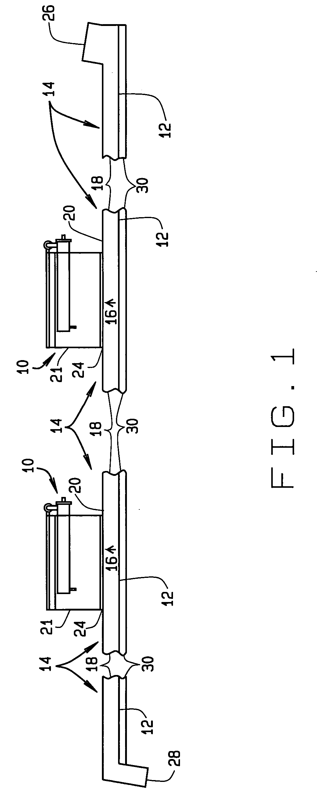
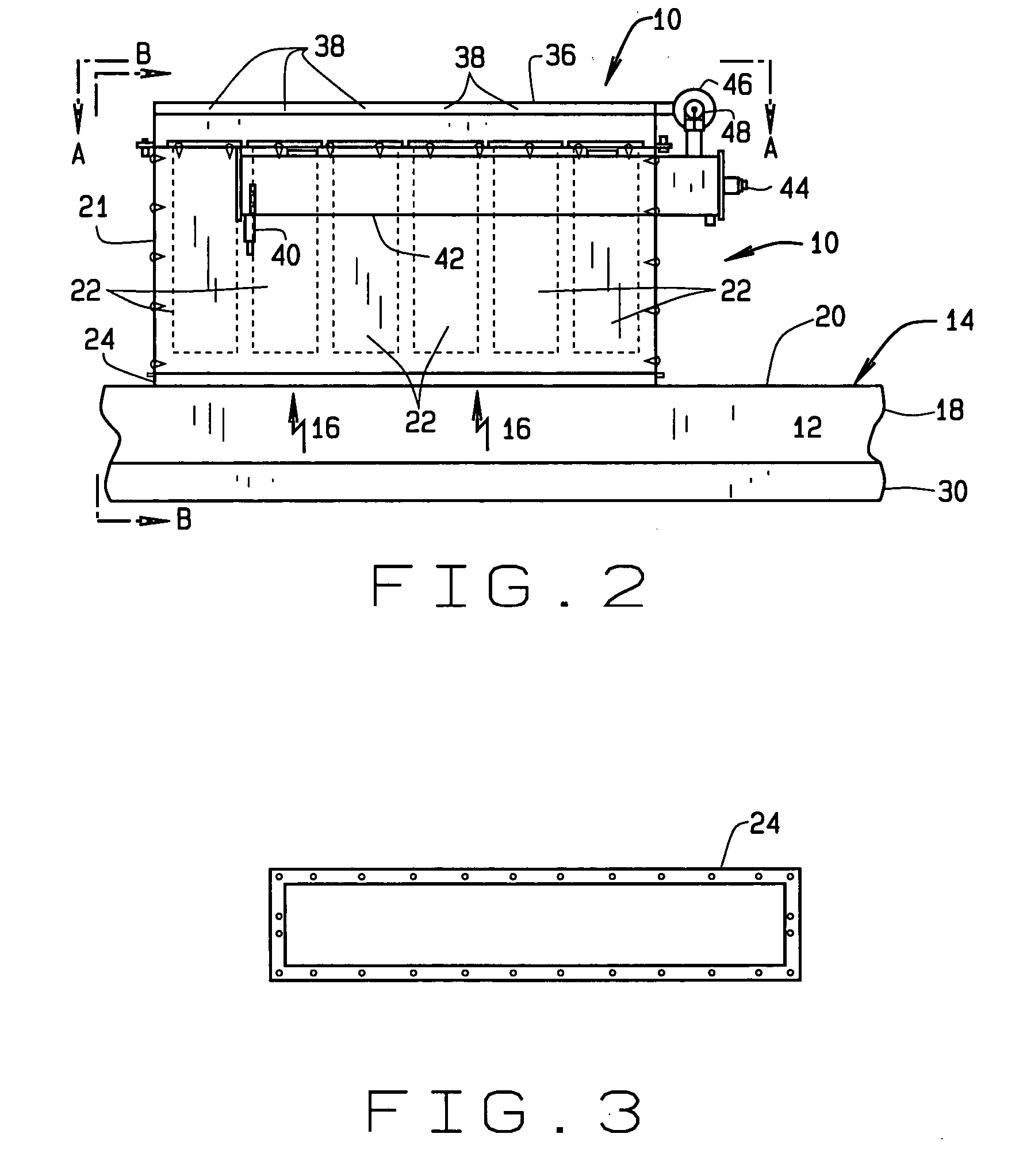
[0016] Referring to FIG. 1, collector assemblies 10 are used in some configurations of the present invention to depressurize the volume above an air-permeable slide 12 of a pressurized air fluidizing conveyor 14 (air conveyor) after the pressurized air has performed its function. More particularly, some configurations of the present invention advantageously vent spent, dust-laden air 16 above slide 12 in a top or upper chamber 18 of conveyor 14. This venting is performed without material dust escaping into the atmosphere around the conveyor. Air conveyor 14 is either an existing air conveyor being retrofitted or a new air conveyor. Slide 12 can be any suitable material and is a fabric slide in some configurations.

[0017] Configurations of the present invention provide one or more collector assemblies 10 attached, or attachable, to air conveyor 14. The number and size of collector assemblies 10 can be selected in accordance with the size of air conveyor 14 and how much powdered mater...


PUM

PropertyMeasurementUnit
Timeaaaaaaaaaa
Timeaaaaaaaaaa
Timeaaaaaaaaaa

Abstract

A collector assembly is configured to vent dust-laden air through at least one filter in one direction using pressure in an air conveyor, whereby dust collects on one side of the filter or filters. The collector assembly is further configured to pulse compressed air through the filter or filters in an opposite direction to dislodge the collected dust into the air conveyor without the dislodged dust entering the atmosphere around the air conveyor.

Description

BACKGROUND OF THE INVENTION [0001] This invention relates generally to pollution control and more particularly to methods and apparatus for reducing and recovering dust emissions from air conveyors. [0002] Air conveyors are used for moving very dry, fluid materials, such as powdered substances at cement plants, lime plants, pharmaceutical plants, paint plants, and other facilities. The powdered material being moved is typically very fluid, and resembles face powder in that regard. At least one known fluidizing air conveyor has two chambers joined at a horizontal flange. In fact, the flange is not actually horizontal, but rather is inclined slightly (for example, at 7 to 8 degrees) to allow the conveyor to advantageously utilize the force of gravity to move the fluidized material from a silo or other material reservoir. An air-permeable fabric or felt is sandwiched in the flange. Below the flange, one of the chambers is an open metal box with pressurized air covered by the fabric. Be...

Claims


Application Information

Patent Timeline
IPC IPC(8): B65G53/00
CPCB01D46/002B01D46/0068B01D46/2411B01D46/521B65G53/02B65G69/181B01D46/58B01D46/71
Inventor MCCONNELL, LARRY D.
Owner BHA ALTAIR
Why Eureka
Try Eureka