
Methods, devices and systems for high-speed autonomous vehicle and high-speed autonomous vehicle

a technology of autonomous vehicles and high-speed vehicles, applied in the direction of distance measurement, surveying and navigation, instruments, etc., can solve the problems of robots being restricted, the technology not keeping up with the demands presented, and the robots being unable to traverse off-road terrain at higher speeds. achieve the effect of high resolution

Inactive Publication Date: 2006-05-04
CARNEGIE MELLON UNIV
View PDF12 Cites 40 Cited by
  • Summary
  • Abstract
  • Description
  • Claims
  • Application Information

AI Technical Summary

Benefits of technology

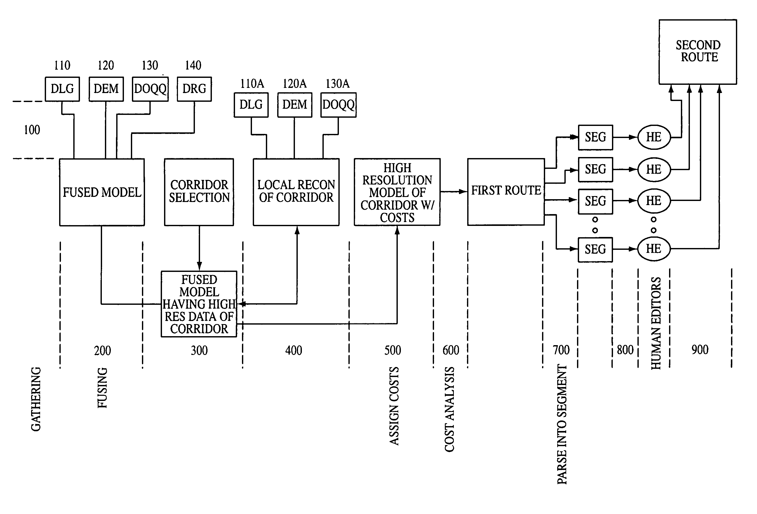
[0014] It is still another object of the invention to provide systems, devices, and methods to enable the generation of a route with extremely high resolution without undue strain on resources such as processing, system memory, and human editing time.

Problems solved by technology

However, such robots are restricted in that most are capable of traveling only at low speeds.
Robots capable of traversing off-road terrain at higher speeds have been restricted in that the technology has only allowed such robots to travel through simple off-road scenarios.
However, the technology has not kept pace with the demands presented by high-speed off-road travel.
Until now, autonomous off-road vehicles have fallen short of performance ambitions.
Diverse and changing topology coupled with terrain induced excitations can affect the level of accuracy of data collected by such instrumentation, and high-speed AOT has been limited until now because of the inadequate methods and mechanics employed to stabilize such instrumentation.
Until now, the ability to remain actively fixed on a target under high-speed off-road conditions has been severely limited.
Such prior methods have drawbacks, however, including reliance on low-resolution data and the inability to account for changes to the rehearsed path or for “new” or previously unseen obstacles in the rehearsed path.
Further, at present, there is no system or method that significantly accounts for the dynamic vehicle modeling to provide a pre-planned route and to command a vehicle within the intended route.

Method used


Image

  • Methods, devices and systems for high-speed autonomous vehicle and high-speed autonomous vehicle
  • Methods, devices and systems for high-speed autonomous vehicle and high-speed autonomous vehicle
  • Methods, devices and systems for high-speed autonomous vehicle and high-speed autonomous vehicle

Examples


Embodiment Construction

[0035] The presently preferred embodiment employs the technology discussed herein into an autonomous off-road vehicle that is able to travel at high-speeds. The person of ordinary skill in the art will appreciate that the definition of “high-speed” depends on many variables and may change with time. One of the meanings of “high-speed” relevant to the presently preferred embodiment of the invention relates to the speed that an autonomous off-road robotic vehicle can travel over an unrehearsed route, over off-road terrain that is non-graded and non-flat, and without “blindly” following GPS waypoints. Under such conditions, a present value for an average “high-speed” is approximately 50 mph. Discussed below will be the presently preferred embodiments of the various methods, systems, and devices utilized on the high-speed off-road autonomous vehicle of the present invention.

[0036] The invention provides a novel sensory stabilization means and method for the stabilization of the sensory...


PUM


Abstract

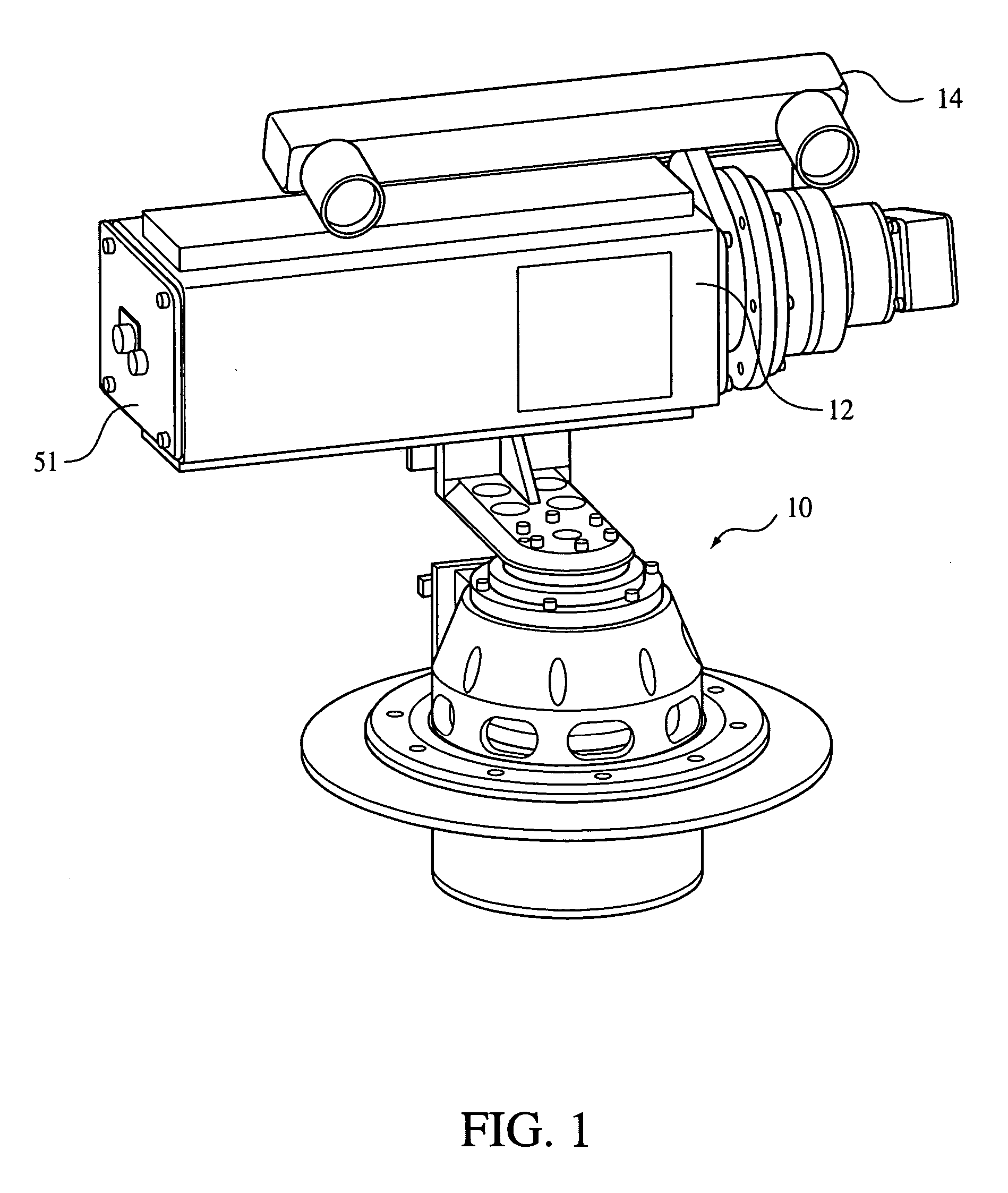
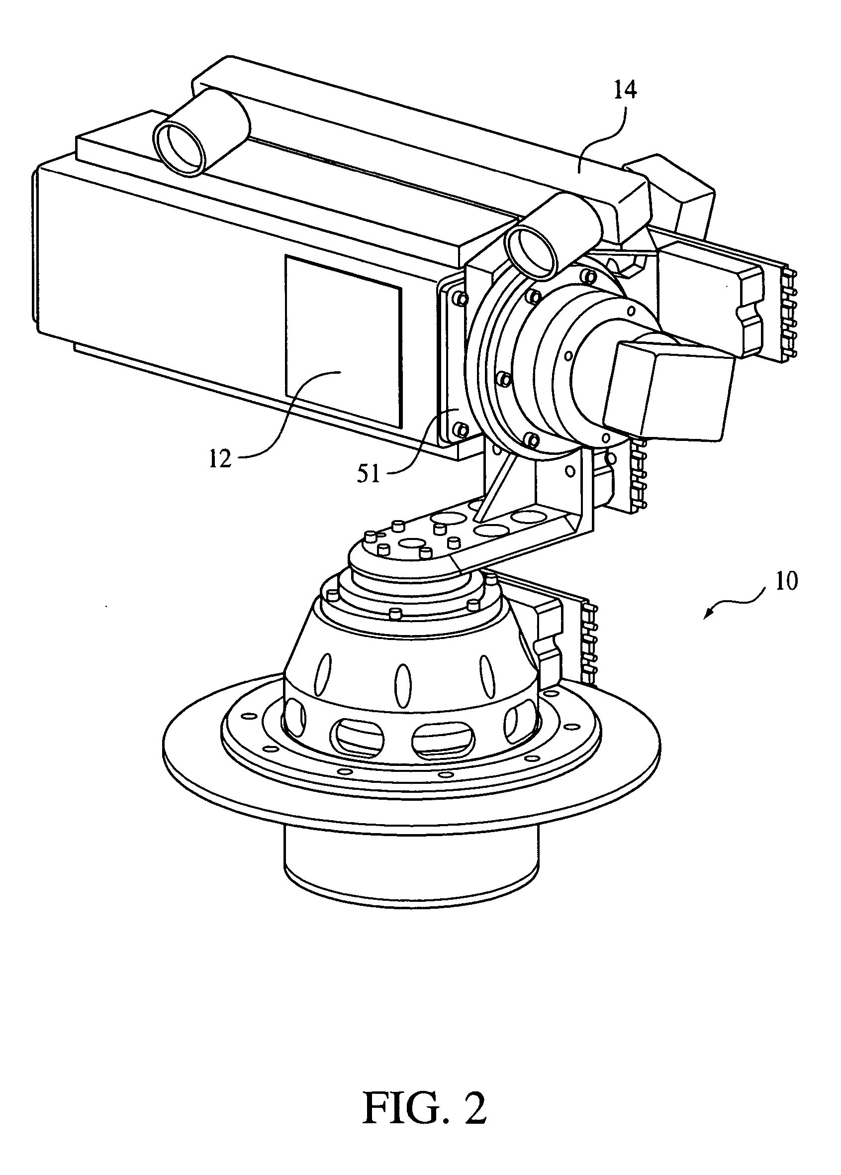
The invention comprises an autonomous off-road vehicle capable of traveling at high speeds. Preferred embodiments of the invention comprise a system for sensory instrument stabilization comprises three axis assemblies movable about three orthogonal axes. The invention also comprises novel methods for generating a high accuracy route for a robotically controlled vehicle. Other aspects of the invention include drive time, perception-based path adjustments to steer a robotic vehicle within an intended corridor. Another embodiment of the invention comprises the consideration of vehicular dynamics in generating a high accuracy route and in steering a robotic vehicle within an intended corridor.

Description

CLAIM OF PRIORITY [0001] This invention claims priority to a United States provisional application having Ser. No. ______ filed Nov. 2, 2004.FIELD OF THE INVENTION [0002] The invention relates generally to methods, devices, and systems for the navigation of robotic non-supervised autonomous vehicles. Specifically, the invention relates to a vehicle equipped with methods, devices, and systems that render the vehicle capable of high-speed autonomous traversal over unrehearsed terrain. Aspects of the invention can, however, apply to non autonomous robotic vehicles and would therefore apply to the fields of driver assistance and telematics. BACKGROUND OF THE INVENTION [0003] Robots capable of traversing through rough terrain are known. However, such robots are restricted in that most are capable of traveling only at low speeds. Robots capable of traversing off-road terrain at higher speeds have been restricted in that the technology has only allowed such robots to travel through simple ...

Claims


Application Information

Patent Timeline
IPC IPC(8): G01C22/00
CPCG05D1/027G05D1/0272G05D1/0274G05D1/024
Inventor WHITTAKER, WILLIAM L.URMSON, CHRISSMITH, BYRON KEITHKATO, HIROKIMILLER, NICHOLAS MICHAELPETERSON, KEVIN MICHAELJOHNSON-ROBERSON, MATTHEW KAIHODGE, VANESSACLARK, MICHAEL NEILANHALT, JOSHUA
Owner CARNEGIE MELLON UNIV
Learn More