
Self-balancing, load-distributing helmet structure

Inactive Publication Date: 2006-05-11
MJD INNOVATIONS
View PDF14 Cites 43 Cited by
  • Summary
  • Abstract
  • Description
  • Claims
  • Application Information

AI Technical Summary

Benefits of technology

[0009] The present invention dramatically addresses this serious problem situation. It does so, as will be learned from discussion below, read in conjunction with the accompanying drawing figures, by linking to a suspension frame and pad environment, as just above described, a laterally and longitudinally (front-to-rear, etc.) self-adjusting, self-“load-balancing” chin-strap structure. There is no absolute “fixed” configuration for such a chin-strap structure. Rather, this structure automatically “senses” the specific, current head-to-pad engagement condition immediately on the occurrence of its being tightened “into place” to achieve helmet / head stabilization. No matter the pad “condition” (population, disposition) inside a helmet, the cooperative, self-adjusting chin-strap structure and system of the present invention assures at all times that all installed pads will fully and correctly engage the wearer's head.

Problems solved by technology

There is no absolute “fixed” configuration for such a chin-strap structure.

Method used


Image

  • Self-balancing, load-distributing helmet structure
  • Self-balancing, load-distributing helmet structure
  • Self-balancing, load-distributing helmet structure

Examples


Embodiment Construction

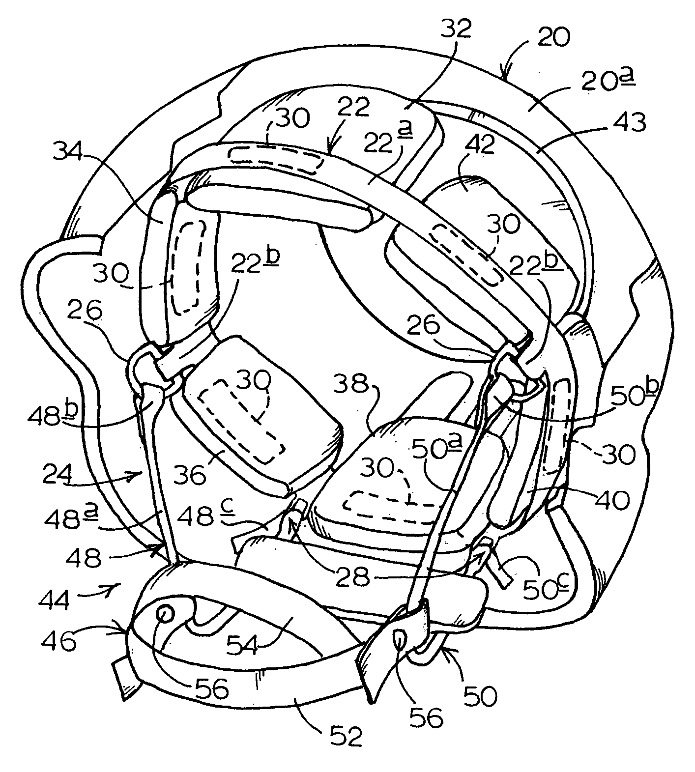
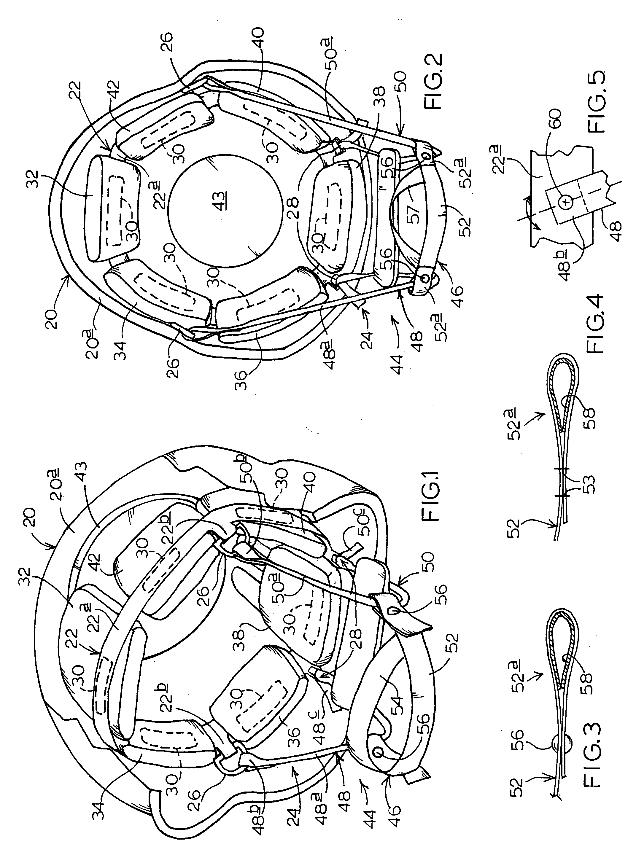
[0018] Turning attention first to FIGS. 1 and 2, indicated generally at 20 is a military helmet having a shell 20a inside of which is suitably anchored an all-around suspension, or suspension frame, 22 which, herein, is made in accordance with the teachings of above-referred-to, prior-issued, U.S. Pat. No. 6,681,402 B2. Shell 20a in FIG. 1 is partially broken away better to reveal the representative operative environment wherein the self-load-balancing self-adjusting, load-distributing helmet safety and support system 24 of this invention is installed for use.

[0019] Suspension 22, in general terms, includes a wrap-around, elongate band 22a which is directly and appropriately anchored to shell 20a, with this band including a pair of forward, lateral strap-end attaching structures 22b which, as illustrated particularly in FIG. 1, receive and hold freely dangling, conventional strap-attaching D-rings, such as the two D-rings shown at 26. While these D-rings are per se conventional, th...


PUM


Abstract

A self-seeking, load-distributing, load-balancing and shock-managing head-engaging system for use inside, and in association with, the shell of a helmet, including (a) a collection of configurationally changeable, shock-absorbing pads removeably and changeably attached / attachable effectively as a variable distribution to the inside of such a shell, and (b) a cinchable, self-seeking / adjusting, self-load-balancing and load distributing chin-strap subsystem operatively associated with the pad distribution, and also attached to the shell. This sub-system is sensitive to the then-particularities of such a pad distribution, and is operable, on cinching of the subsystem through the simple act of pulling on just two strap ends, to stabilize the associated helmet shell on the head of a wearer, with all of the pads in the then-distribution of pads being thereby drawn into proper, defined, shock-managing, load-distributing and load-balancing condition relative to the wearer's head.

Description

CROSS-REFERENCE TO RELATED APPLICATION [0001] This application claims priority to prior-filed, copending U.S. Provisional Patent Application Ser. No. 60 / 626,702, filed Nov. 9, 2004, for “Self-Balancing, Load-Distributing Helmet Structure”. The entire disclosure content of that prior-filed provisional application is hereby incorporated herein by reference.BACKGROUND AND SUMMARY OF THE INVENTION [0002] This invention relates to protective helmet construction, and in particular to a novel combined self-seeking, load-distributing, load-balancing and shock-managing head-engaging system employable within the shell of a helmet. A preferred and best mode embodiment of the invention is described and illustrated herein in the context of a military helmet—an environment wherein the invention has been found to offer special utility. Incorporated by reference into this text, are the disclosures of U.S. Pat. No. 6,467,099 B2 for “Body-Contact Cushioning Interface Structure”, and U.S. Pat. No. 6,6...

Claims


Application Information

Patent Timeline
IPC IPC(8): A42B3/00
CPCA42B3/08A42B3/127A42B3/145
Inventor DENNIS, MICHAEL R.PAASCHE, GERHARD
Owner MJD INNOVATIONS
Learn More