Cylinder lock
- Summary
- Abstract
- Description
- Claims
- Application Information
AI Technical Summary
Benefits of technology
Problems solved by technology
Method used
Image

Examples
Embodiment Construction
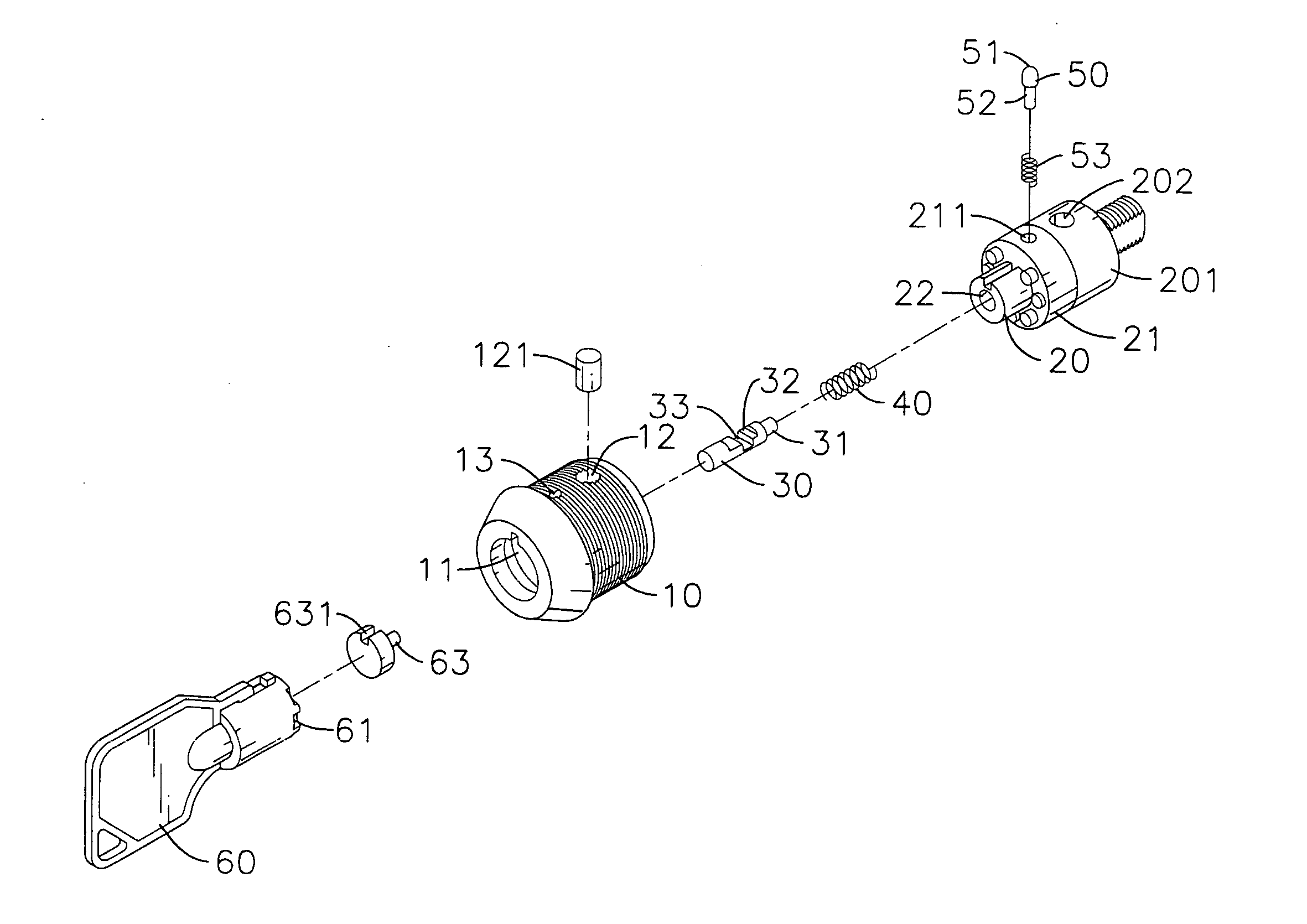
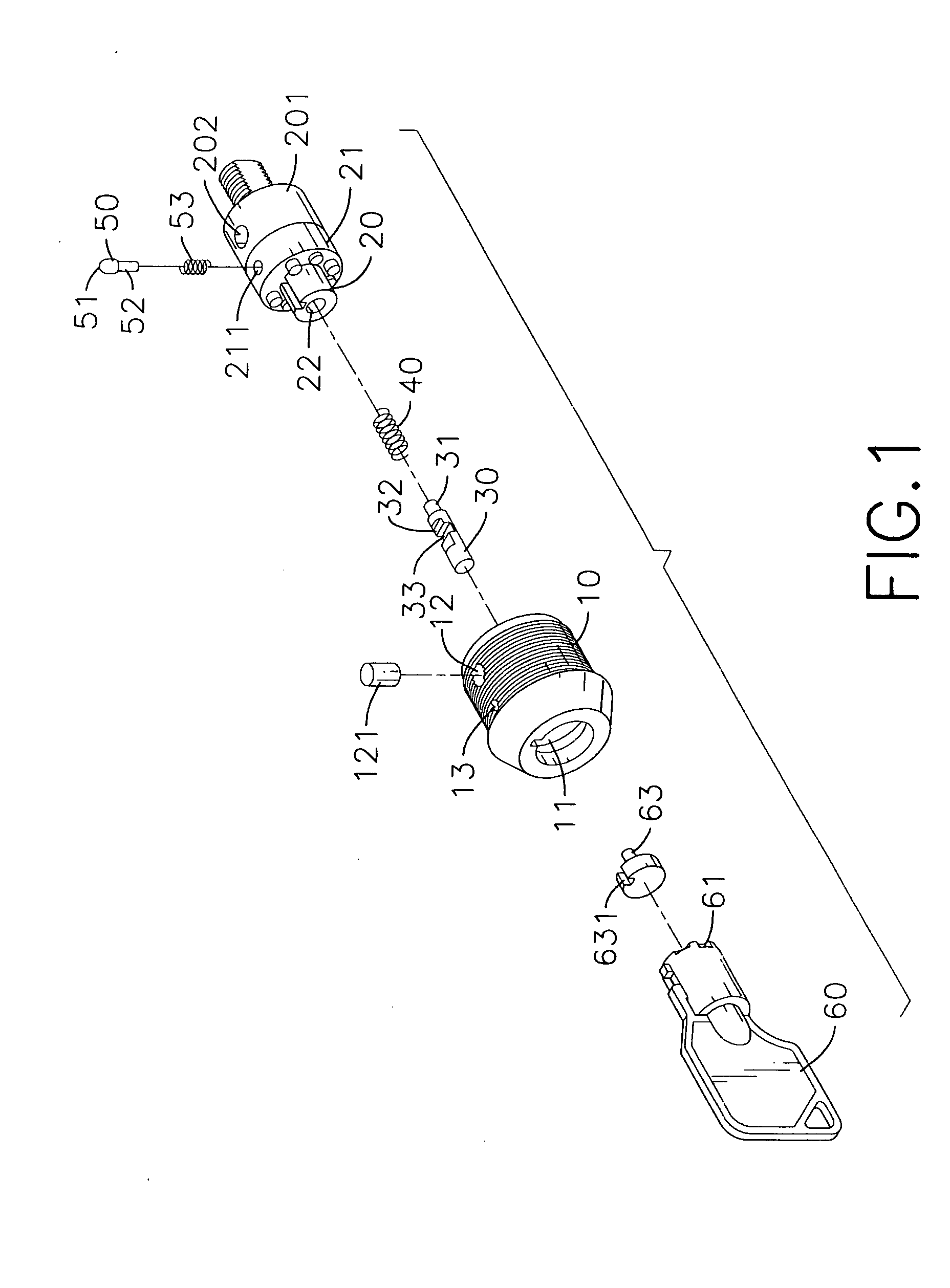
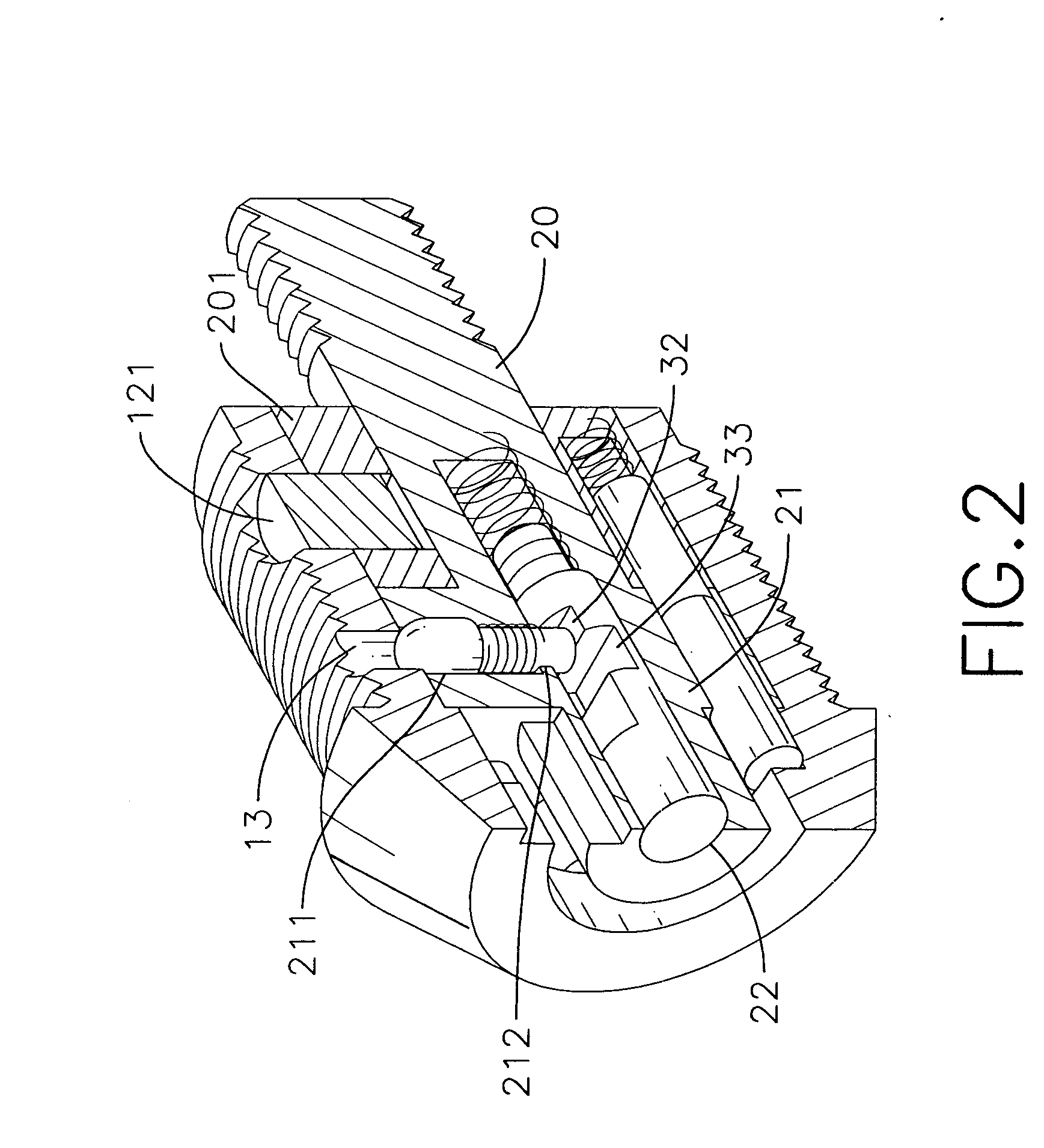
[0024] With reference to FIGS. 1-2, the cylinder lock in accordance with the present invention has a lock housing (10) with a chamber (11). The chamber (11) is defined with a plurality of segments with various diameters. A locking core (20) is received in the chamber (11) and has a structure similar to the conventional locking core.
[0025] A first disk (21) is integrally formed outside the locking core (20), and a second disk (201) is rotatably provided outside the locking core (20) and behind the first disk (21). Multiple first pins and second pins in longitudinally aligned pairs of first and second pins are received in the first disk (21) and the second disk (201) respectively. Multiple springs are received in the second disk (201) to respectively push the second pins towards the first pins.
[0026] The locking housing (10) has a positioning hole (12) and a latching hole (13) radially defined therethrough. A first orifice (211) is radially defined in an outer periphery of the first...
PUM
 Abstract
Description
Claims
Application Information
 - R&D
- Intellectual Property
- Life Sciences
- Materials
- Tech Scout
- Unparalleled Data Quality
- Higher Quality Content
- 60% Fewer Hallucinations
Browse by: Latest US Patents, China's latest patents, Technical Efficacy Thesaurus, Application Domain, Technology Topic, Popular Technical Reports.
© 2025 PatSnap. All rights reserved.Legal|Privacy policy|Modern Slavery Act Transparency Statement|Sitemap|About US| Contact US: help@patsnap.com