Method and system for presentation of content from one cellular phone to another through a computer network
- Summary
- Abstract
- Description
- Claims
- Application Information
AI Technical Summary
Benefits of technology
Problems solved by technology
Method used
Image
Examples
first embodiment
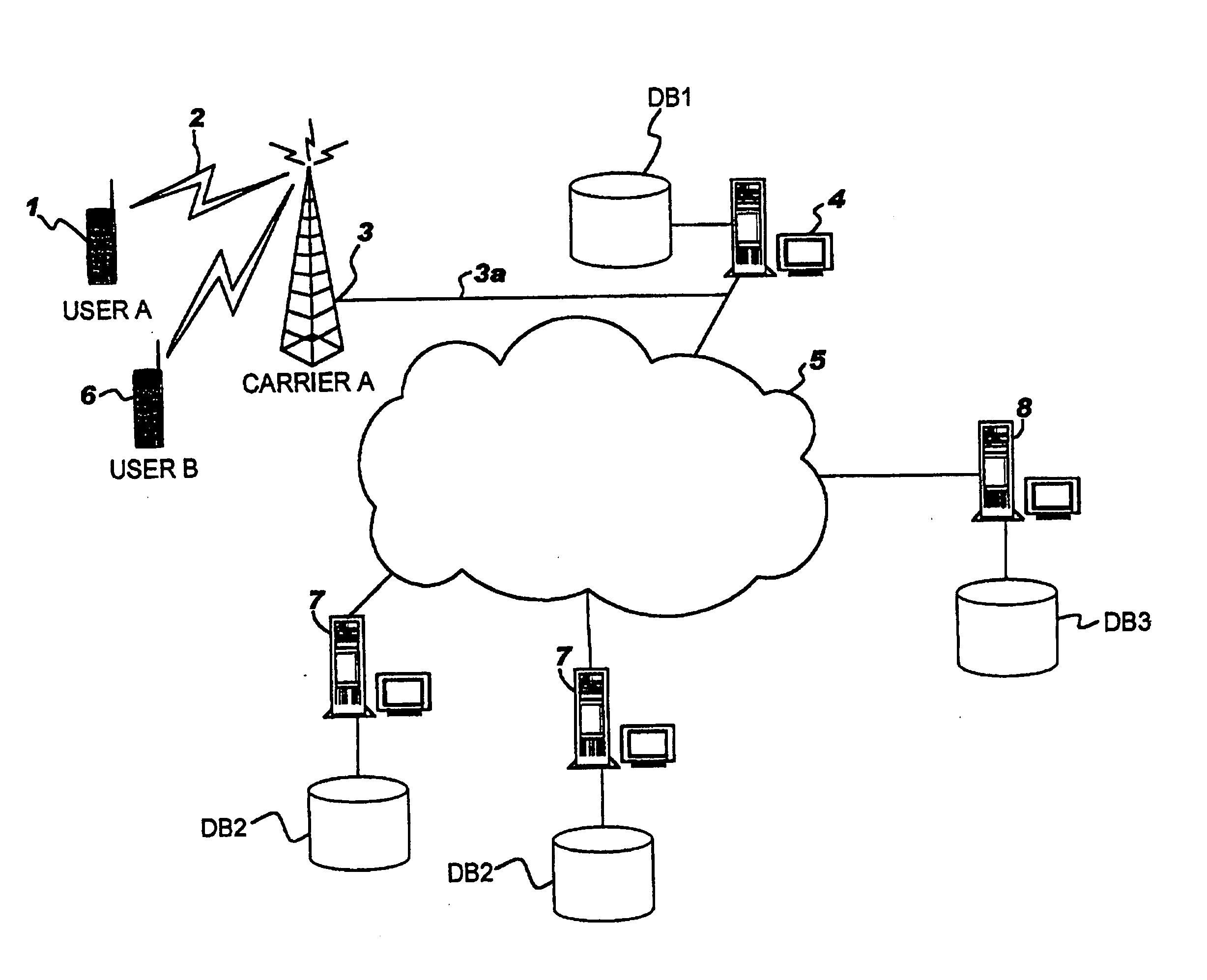
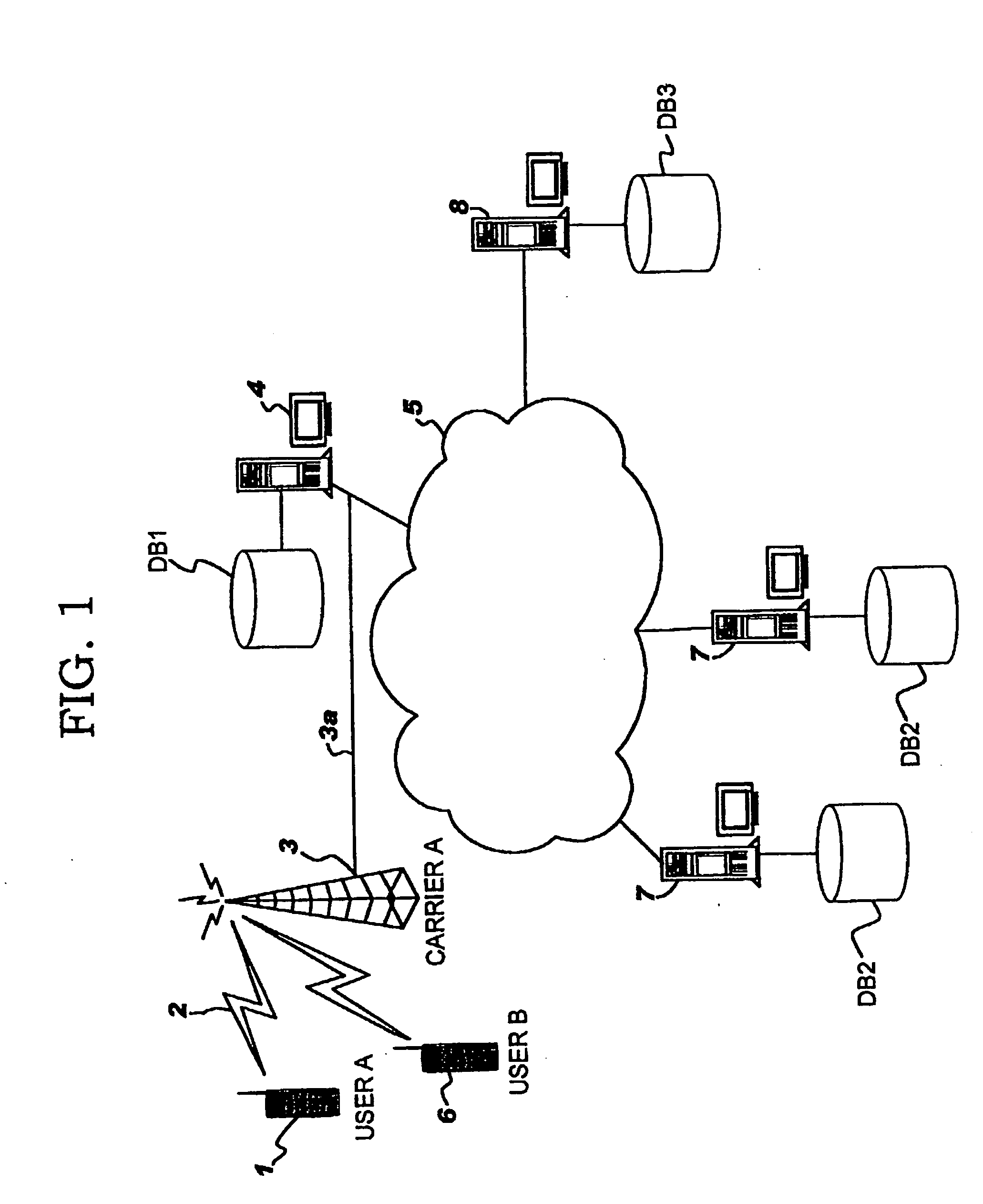
[0045]FIG. 1 is a schematic block diagram of a content presentation system in the present invention. The content presentation system of the present invention shown in FIG. 1 is configured by a cellular phone 1; an antenna 3 installed by a specific carrier to receive radio communications from this cellular phone 1 via a network 2 provided by a predetermined carrier; a public telephone line 3a used to transfer a signal received by the antenna 3; and such a network 5 such as the Internet connected to this network 2 via a carrier server 4 installed at the carrier.
[0046] The network 5 may be the Internet, as well as an optical communication network and a LAN / WAN that uses a proper communication protocol so as to send / receive data and information remotely. One of the protocols employable for such communications is, for example, TCP / IP.
[0047] The cellular phone 1 may be any type that can access a network 5 such as the Internet. For example, the cellular phone 1 may be replaced with a cell...
second embodiment
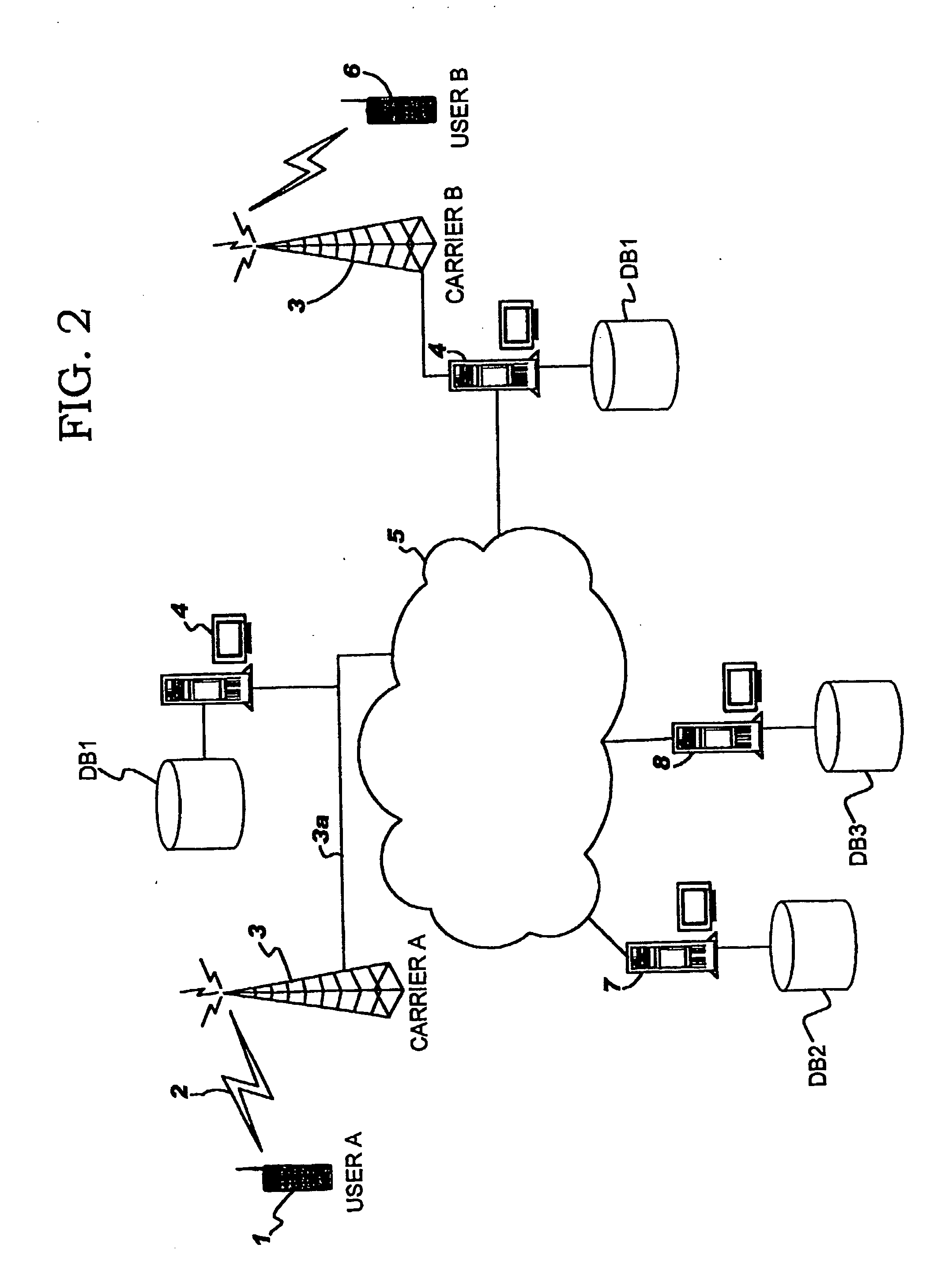
[0054]FIG. 2 illustrates the present invention. In FIG. 1, the cellular phones 1 and 6 receive content and services via the network 2 of the same carrier. However, the present invention also enables content to be provided from different carriers so that the cellular phone 1 can use the network of carrier A, while the cellular phone 6 can use the network of carrier B.
[0055]FIG. 3 shows a configuration of the database DB1 included in the carrier server 4 installed at a carrier site. The database DB1 is configured by a charging database 10, a user certification database 11, and a content pool database 12. The content pool database 12 is used to store content temporarily when the cellular phone 6 of the user B cannot be connected or fails in connection.
[0056]FIG. 4 is a schematic view of the data structure of the charging database 10 shown in FIG. 3. The charging database comprises data class 10a (provider ID and name) and data class 10b (user ID, provider ID (each provider of content ...
PUM
 Abstract
Description
Claims
Application Information
 - R&D
- Intellectual Property
- Life Sciences
- Materials
- Tech Scout
- Unparalleled Data Quality
- Higher Quality Content
- 60% Fewer Hallucinations
Browse by: Latest US Patents, China's latest patents, Technical Efficacy Thesaurus, Application Domain, Technology Topic, Popular Technical Reports.
© 2025 PatSnap. All rights reserved.Legal|Privacy policy|Modern Slavery Act Transparency Statement|Sitemap|About US| Contact US: help@patsnap.com


