Control apparatus for internal combustion engine

a control apparatus and internal combustion engine technology, applied in mechanical devices, electric control, machines/engines, etc., can solve the problems of poor mixing of air-fuel mixture formed by the fuel injected from the in-cylinder injector, unstable combustion,

Active Publication Date: 2006-05-11
TOYOTA JIDOSHA KK
View PDF5 Cites 35 Cited by
  • Summary
  • Abstract
  • Description
  • Claims
  • Application Information

AI Technical Summary

Benefits of technology

[0012] An object of the present invention is to provide a control apparatus for an internal combustion engine conducting fuel injection using one or both of a first fuel injection mechanism for injecting a fuel into a cylinder and a second fuel injection mechanism for injecting a fuel into an intake manifold, capable of solving the problem associated with a combination of stratified charge combustion and homogeneous combustion, and also capable of solving the problem associated with homogeneous combustion in the case of a direct injection engine.

Problems solved by technology

In particular, in the low-speed and high-load region, mixing of an air-fuel mixture formed by the fuel injected from the in-cylinder injector is poor, and such inhomogeneous air-fuel mixture within the combustion chamber may lead to unstable combustion.

Method used


Image

  • Control apparatus for internal combustion engine
  • Control apparatus for internal combustion engine
  • Control apparatus for internal combustion engine

Examples


Embodiment Construction

[0037] Hereinafter, embodiments of the present invention will be described with reference to the drawings. In the following description, the same parts have the same reference characters allotted and also have the same names and functions. Thus, detailed description thereof will not be repeated.

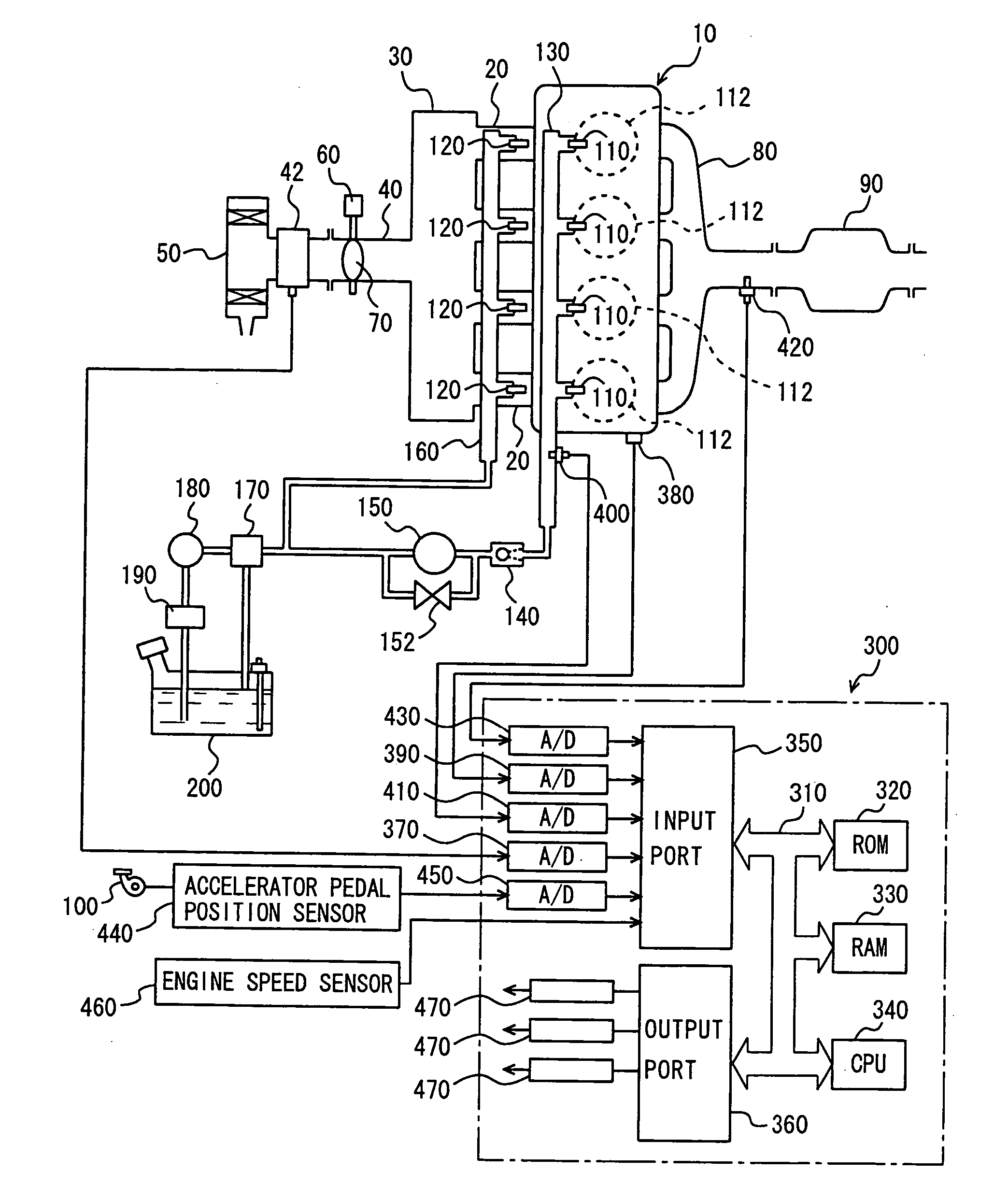
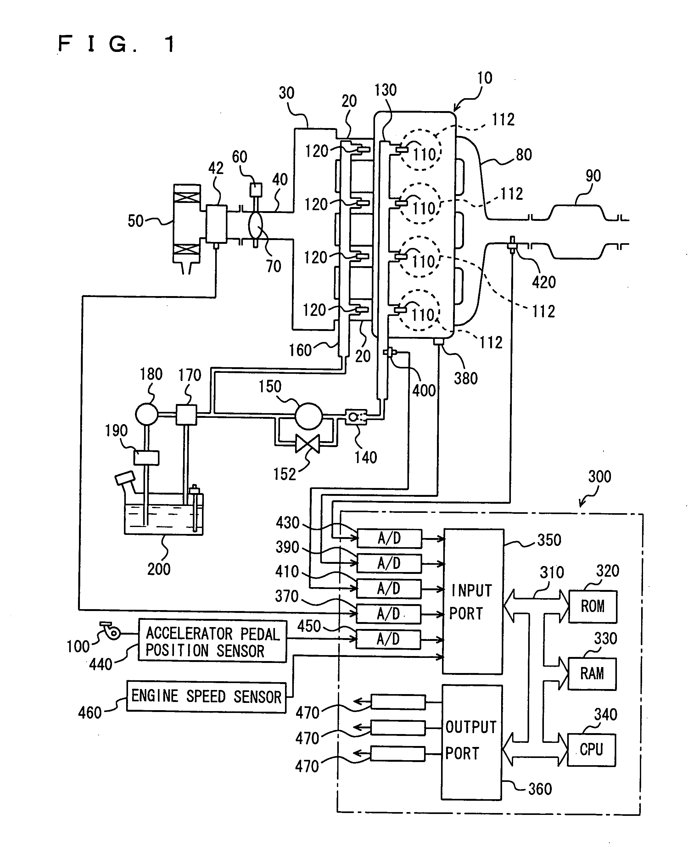
[0038]FIG. 1 is a schematic configuration diagram of an engine system that is controlled by an engine ECU (Electronic Control Unit) implementing the control apparatus for an internal combustion engine according to an embodiment of the present invention. In FIG. 1, an in-line 4-cylinder gasoline engine is shown, although the application of the present invention is not restricted to such an engine.

[0039] As shown in FIG. 1, the engine 10 includes four cylinders 112, each connected via a corresponding intake manifold 20 to a common surge tank 30. Surge tank 30 is connected via an intake duct 40 to an air cleaner 50. An airflow meter 42 is arranged in intake duct 40, and a throttle valve 70 dri...


PUM


Abstract

An engine ECU executes a program including the step of detecting an engine coolant temperature (THW), the step of selecting a map for a warm state as the map for calculating a fuel injection ratio (or a DI ratio) r when the engine coolant temperature (THW) is equal to or higher than a temperature threshold value (THW(TH)) (YES in S110), the step of selecting a map for a cold state as the map for calculating the fuel injection ratio (or the DI ratio) r when the engine coolant temperature (THW) is lower than the temperature threshold value (THW(TH)) (NO in S110), and the step of calculating the fuel injection ratio between the in-cylinder injector and the intake manifold injector (or the DI ratio) r based on the engine speed, load factor, and the selected map.

Description

[0001] This nonprovisional application is based on Japanese Patent Application No. 2004-328108 filed with the Japan Patent Office on Nov. 11, 2004, the entire contents of which are hereby incorporated by reference. BACKGROUND OF THE INVENTION [0002] 1. Field of the Invention [0003] The present invention relates to a control apparatus for an internal combustion engine having a first fuel injection mechanism (an in-cylinder injector) for injecting a fuel into a cylinder and a second fuel injection mechanism (an intake manifold injector) for injecting a fuel into an intake manifold or an intake port, and relates particularly to a technique for determining a fuel injection ratio between the first and second fuel injection mechanisms. [0004] 2. Description of the Background Art [0005] An internal combustion engine having a first fuel injection valve (an intake manifold injector in the background art) for injecting a fuel into an intake manifold of the engine and a second fuel injection v...

Claims


Application Information

Patent Timeline
Patent Type & Authority Applications(United States)
IPC IPC(8): F02B17/00F02B7/00F02M51/00
CPCF01N3/28F02D41/024F02D41/3029F02D41/3076F02D41/3094F02M63/029F02M69/046F02M69/462Y02T10/26Y02T10/12F02D41/02F02D41/30
Inventor SATOU, FUMIKAZUIKOMA, TAKUYA
Owner TOYOTA JIDOSHA KK
Why Eureka
Try Eureka