Anti-tipover device

a technology of anti-tipover and anti-tipover plate, which is applied in the direction of instruments, furniture parts, machine supports, etc., can solve the problems of causing tremendous force on the bookshelf, and affecting the comfort of guests, so as to mitigate the occurrence of mechanical fracture and mitigate the generation of torque

Active Publication Date: 2006-05-11
HANGMAN PRODS
View PDF6 Cites 28 Cited by
  • Summary
  • Abstract
  • Description
  • Claims
  • Application Information

AI Technical Summary

Benefits of technology

[0010] The present invention specifically addresses and alleviates the above-referenced deficiencies associated with the use of prior art furniture anti-tipover devices. More particularly, the present invention is an improved anti-tipover device configured for more evenly distributing a mechanical load through the device to mitigate the occurr...

Problems solved by technology

In such cases, an accident may have harmful effects for the guests, as well as detrimental consequences for the hotel.
In this example, there are tremendous forces on the bookshelf where the anti-tipover device is connected.
If the stabilization equipment is not properly configured, it may fail due to the forces of the falling bookshelf.
Thus, an improperly configured device under such forces may import relatively high shear forces or produce large torques (i.e. bending forces) on the screws which may ultimately result in device failure.
Currently, there are only a few configurations of anti-tipover devices that are used to stabilize objects in the event of an earthquake or when children climb thereon.
Due to its configuration, this device only prevents tipovers during minor tremors, and may snap (i.e., mechanically fracture) during major tremors or when children climb on the furniture.
Another deficiency of the device is that it only incorporates a touch-release securing tab to prevent the plastic strap from slipping out of the brackets.
Significant swaying, contact made when other objects hit the plastic strap, or other foreseeable events common durin...

Method used


Image

  • Anti-tipover device
  • Anti-tipover device
  • Anti-tipover device

Examples


Embodiment Construction

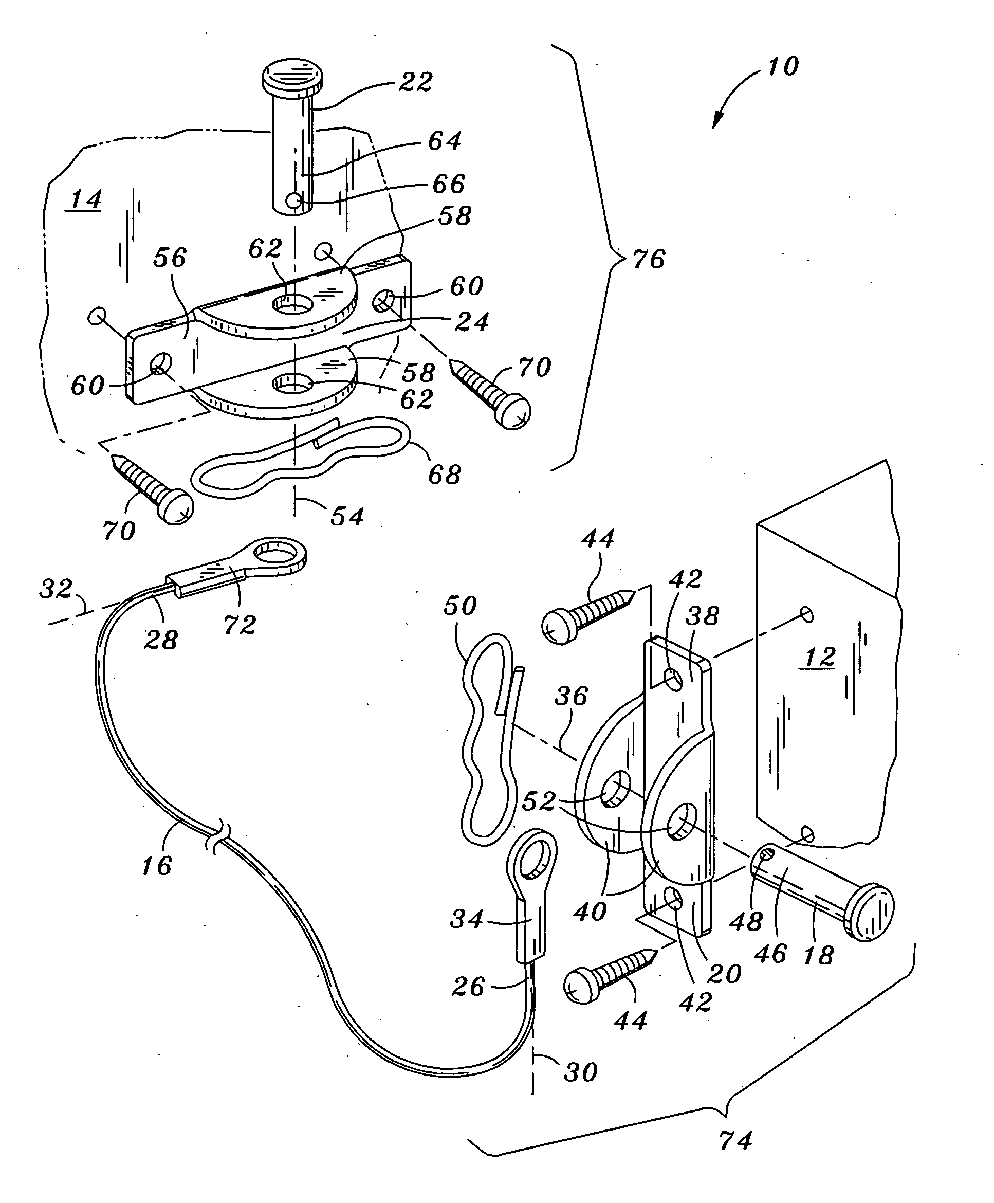
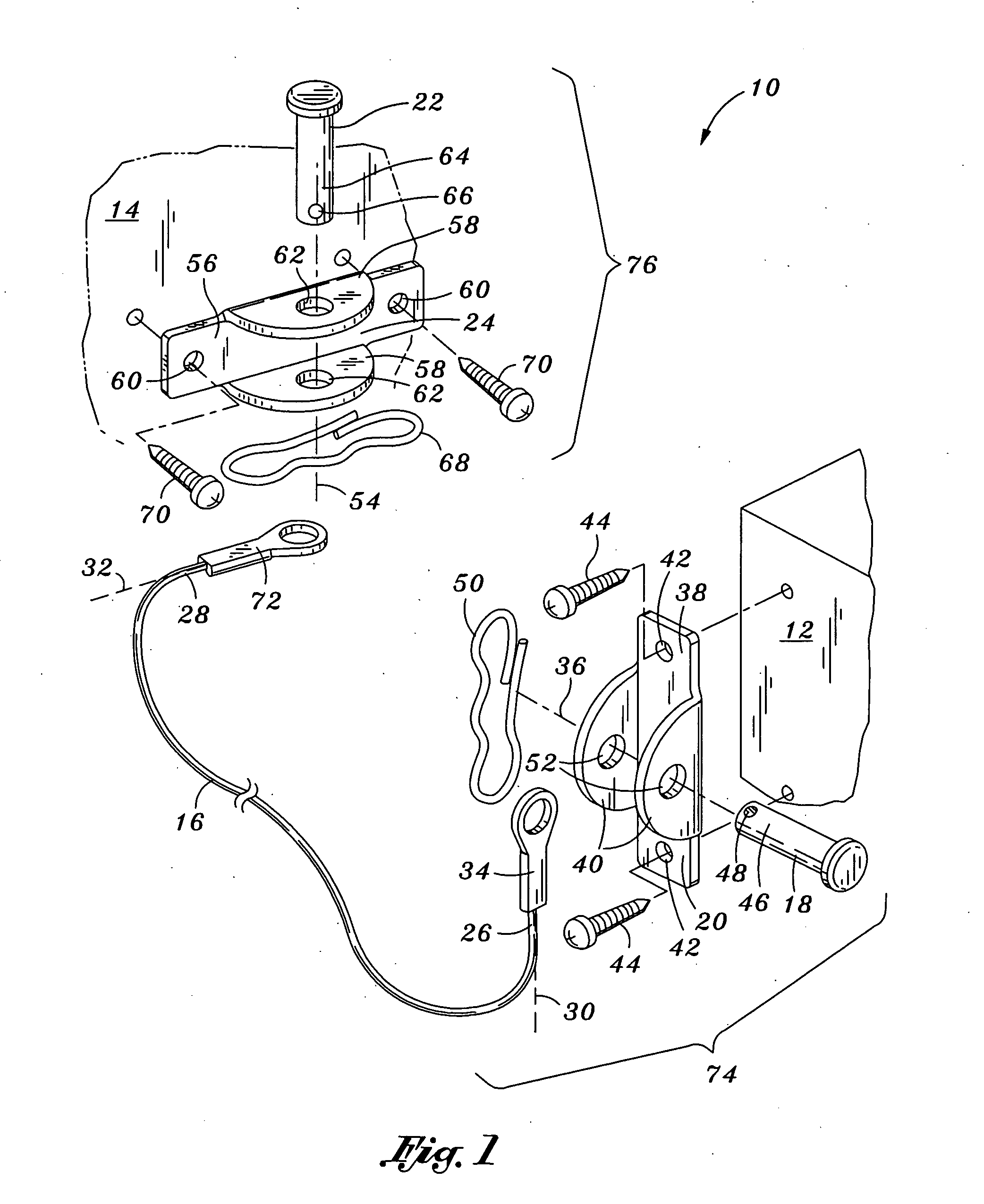
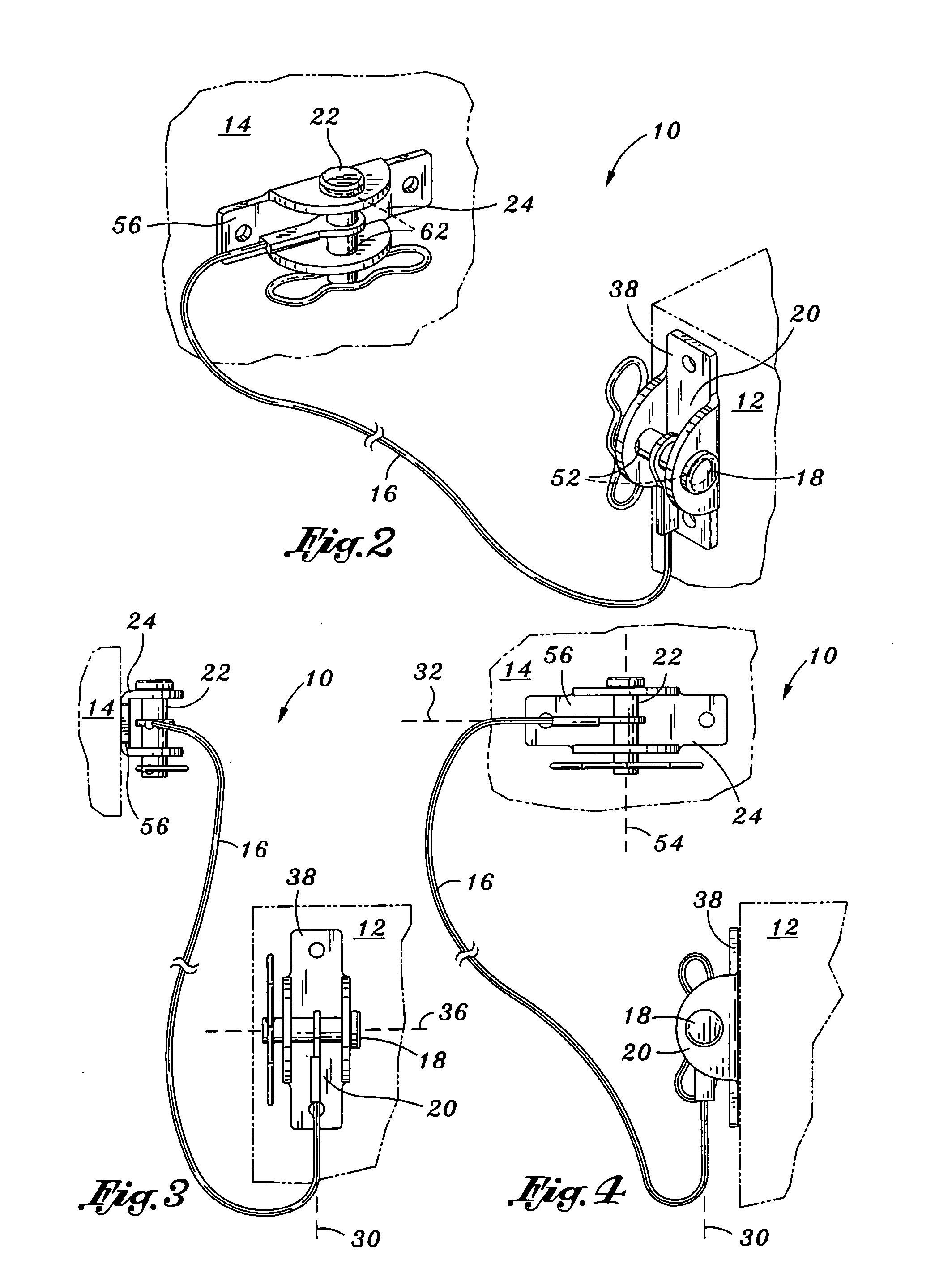
[0026] Referring now to the drawings wherein the showings are for purposes of illustrating preferred embodiments of the present invention only and not for purposes of limiting the same, FIG. 1 is an exploded front perspective view of an anti-tipover device 10 for maintaining an object 12 adjacent a structure 14, such as a wall. Although the present invention is disclosed according to its use with furniture, the anti-tipover device 10 may be used with any object 12 that is disposed adjacent to any structure 14. It is contemplated that the present invention may be used with lamps, vases, grandfather clocks, and other standing objects. Further, the structure 14 disclosed as part of the present invention may include ceilings, floors, or other free standing large objects suitable for stabilizing other smaller or less stable objects.

[0027] According to one aspect of the present invention, provided is the anti-tipover device 10 for retaining the object 12 adjacent the structure 14, the an...


PUM


Abstract

An anti-tipover device for retaining an object adjacent a structure, the anti-tipover device comprising an elongate flexible link element including opposing first and second end sections, the first and second end sections defining first and second longitudinal axes, respectively; first and second pin elements defining first and second rotational axes, respectively, the first and second pin elements being coupled to the respective ones of the first and second end sections with the first and second rotational axes disposed perpendicular to the respective ones of the first and second longitudinal axes, the first and second pin elements being sized and configured with the first and second end sections being pivotable about the respective ones of the first and second pin elements; first and second cable retaining members being attached to the respective ones of first and second pin elements and being mountable to the respective ones of the object and structure.

Description

CROSS-REFERENCE TO RELATED APPLICATIONS [0001] (Not Applicable) STATEMENT RE: FEDERALLY SPONSORED RESEARCH / DEVELOPMENT [0002] (Not Applicable) BACKGROUND OF THE INVENTION [0003] The present invention pertains generally to object stabilization equipment, and more particularly, to a uniquely configured anti-tipover device utilizing a pivotal coupling for mitigating the torque placed on the device while supporting an object adjacent a structure. [0004] Anti-tipover devices are used in many settings to ensure the safety of individuals and the protection of the objects to be stabilized. For example, a hotel may use anti-tipover devices on furniture in its rooms in order to protect any guests from furniture tipover. This concern is of particular importance when considering the likelihood that children might climb the furniture or other objects within the hotel room. It may not be uncommon for children to scale opened drawers of furniture in an effort to reach towards the top of the furnit...

Claims


Application Information

Patent Timeline
IPC IPC(8): G06F13/36
CPCA47B97/00A47B2097/008F16B21/125Y10T292/34Y10T292/37
Inventor GALLIEN, JAMES M.
Owner HANGMAN PRODS
Why Eureka
Try Eureka