Eyeglasses with temple arm supports

a technology of eyeglasses and temples, applied in the field of eyeglasses and eyeglass frames, can solve the problems of unappealing wrinkles in the skin around the nose, contact lenses do not provide any physical protection to the eye, and the use of conventional eyeglass frames is undesirabl

Inactive Publication Date: 2006-05-11
JAMIE SHAHROOZ S +1
View PDF19 Cites 34 Cited by
  • Summary
  • Abstract
  • Description
  • Claims
  • Application Information

AI Technical Summary

Benefits of technology

[0011] To alleviate or improve upon the disadvantages in the prior art, modifications to conventional eyeglass frames comprise a variety of elements to provide support for the frames on other portions of the wearer's face or head. These alternative support points position the eyeglass frames properly without the need for contact with the nasal bridge.

Problems solved by technology

In other cases, the use of conventional eyeglass frames is undesirable because the nose pads cause indentation marks in the skin of the nose, or pull flaccid skin downward, causing cosmetically unappealing wrinkles in the skin around the nose.
The use of contact lenses may alleviate these undesirable consequences, but cannot be worn by or are uncomfortable to many people.
Further, contact lenses do not provide any physical protection to the eye, and hard lenses disposed anterior of the eye are still necessary to provide this protection, as well as vision correction.
This method can be uncomfortable and cause irritation to the skin around the eye socket.
These are capable of supporting the eyeglass frame off the bridge of the nose, but the positioning of the support member along the lower frame edge causes an obstruction to the downward field of vision, a disadvantage especially for those with bifocal lenses.

Method used


Image

  • Eyeglasses with temple arm supports
  • Eyeglasses with temple arm supports
  • Eyeglasses with temple arm supports

Examples


Embodiment Construction

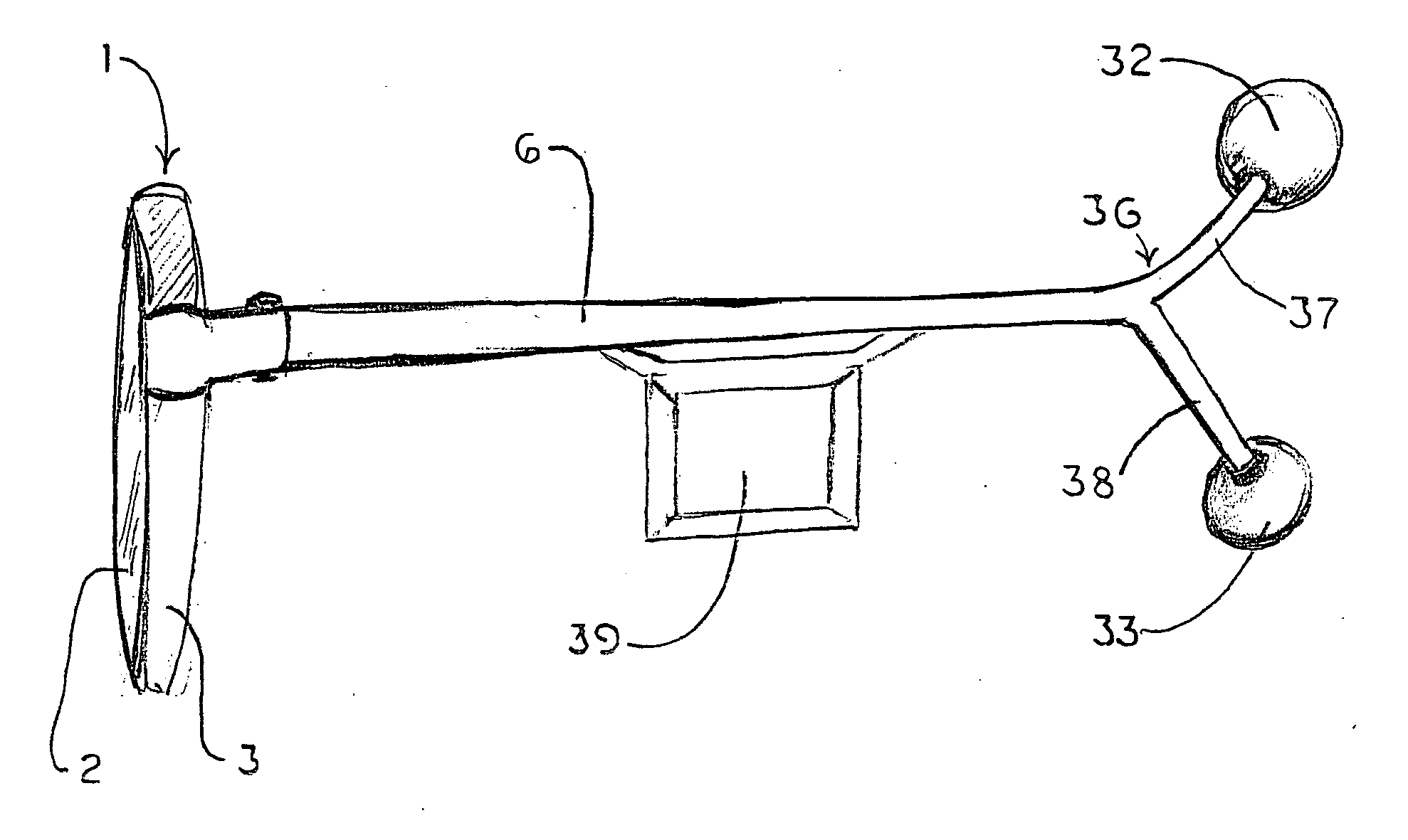
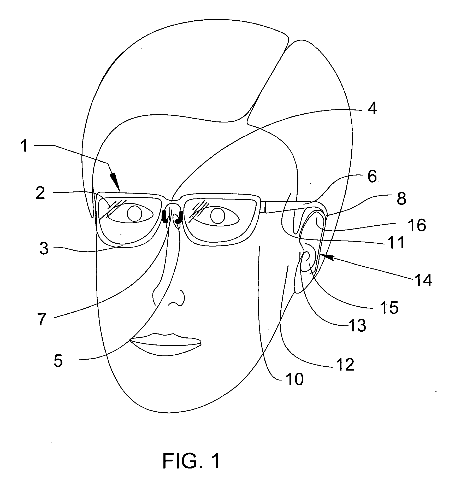
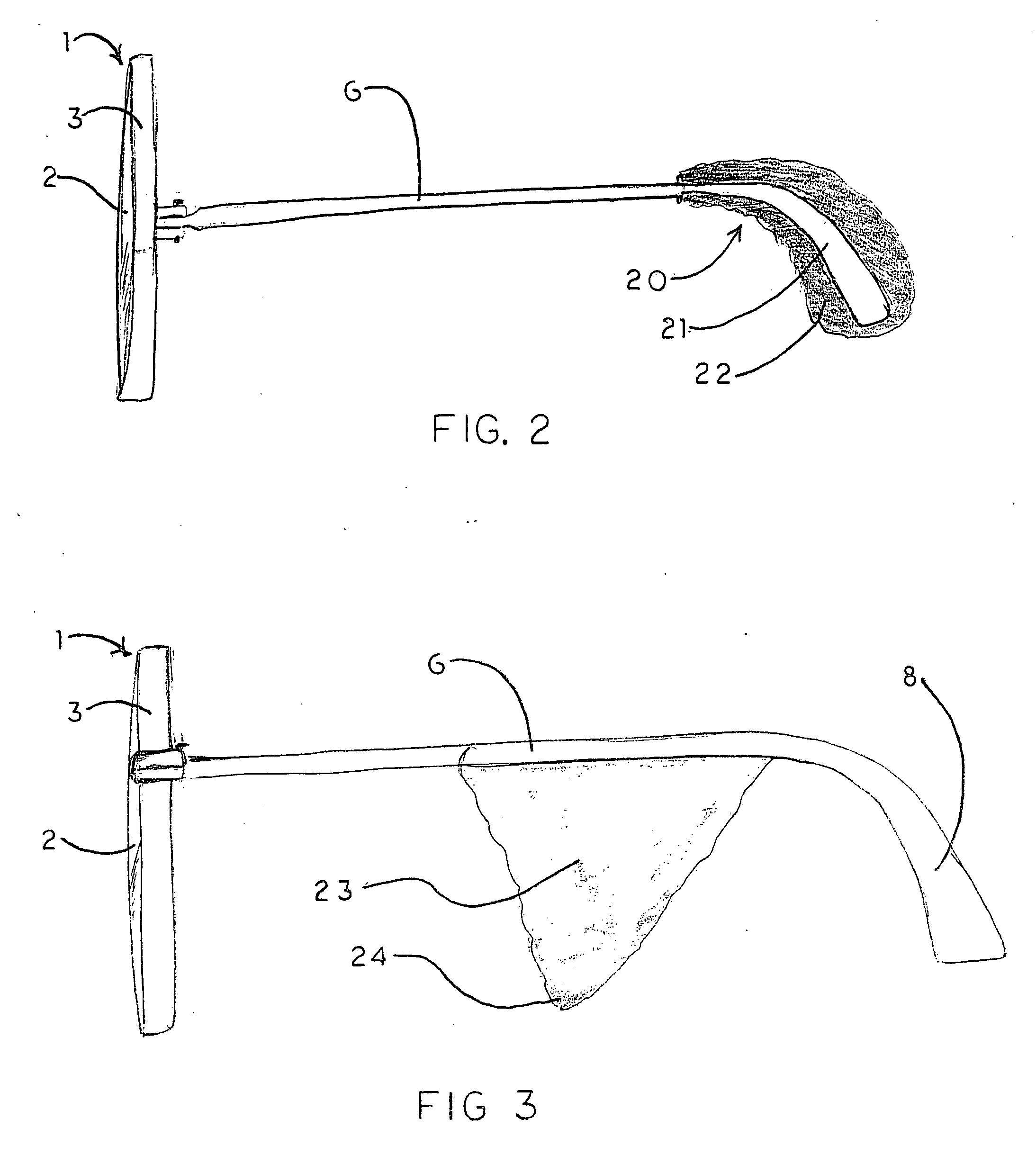
[0036] The following discussion describes in detail one or more embodiments of the invention. The discussion should not be construed, however, as limiting the invention to those particular embodiments, and practitioners skilled in the art will recognize numerous other embodiments as well. The complete scope of the invention is defined in the claims appended hereto.

[0037] As used herein, the following words or terms have the indicated meaning:

[0038]“Inferior” or “inferiorly” means downward, towards the feet.

[0039]“Superior” or “superiorly” means upward, towards the top of the head.

[0040]“Lateral” or “laterally” means horizontally or in a horizontal direction away from the sagittal plane, either left, right, or both.

[0041]“Medial” or “medially” means horizontally or in a horizontal direction towards the sagittal plane of the body.

[0042]“Parasagittal” or “parasagitally” means in a plane parallel to the sagittal plane of the body.

[0043]“Sagittal” or “sagittally” means in a vertic...


PUM


Abstract

Eyeglasses with additional temple arm supports for supporting the frame of a pair of eyeglasses off of and above the nose and nasal bone. The glasses are used by patients recovering from rhinoplasty surgery but who must still have use of eyeglasses which do not contact the nasal bone or nose. In one embodiment, the frame is suspended above the nose by an enhanced counterweighed ear loop. In another embodiment, a stanchion is provided supported by the zygomatic arch to elevate the temple arm. Several embodiments support the temple arm with additional mandibular and temple rests extending orthogonally from the temple. Several additional embodiments replace the conventional ear loop with a pair of support pads at the end of a shortened temple arm. The support pads press against the two bony protuberances on the side of the wearer's head. These protuberances include the zygomatic arch, the mandibular condyle, and the temple. Pressure by the support pads against two of these protuberances provides sufficient support for the entire weight of the eyeglasses. Another embodiment is comprised of a support hoop disposed on the temple arm. The upper arc of the hoop is supported by the temple while the lower arc is supported by the mandible.

Description

BACKGROUND OF THE INVENTION [0001] 1. Field of the Invention [0002] The invention disclosed herein relates to eyeglasses and eyeglass frames with alternative means of support on the face. [0003] 2. Description of the Related Art [0004] Eyeglasses are commonly used to correct vision impairments and as well as to protect the eyes in hazardous environments. Typical eyeglass frames are comprised of common structures for positioning the frame on the face of the wearer. These structures include temple arms, one end of which loops behind the ears, and a nose bridge or nose pads attached to the nose bridge, which rest upon the nose of a wearer. The two ear loops on the temple arms and the nose bridge or pads provide three points of contact with the face of the user, which provides sufficient support to maintain the frames in a desired position and alignment. The nose bridge or pads support a majority of the weight of the frames. The end loops of the temple arms engage with the cartilage of ...

Claims


Application Information

Patent Timeline
Patent Type & Authority Applications(United States)
IPC IPC(8): G02C5/14
CPCG02C3/003G02C5/00G02C5/143G02C11/00G02C11/02
Inventor JAMIE, SHAHROOZ S.JAMIE, SHARON S.
Owner JAMIE SHAHROOZ S
Why Eureka
Try Eureka