
Systems and methods for communicating with bi-nodal network elements

Inactive Publication Date: 2006-05-11
NEXTEL COMMUNICATIONS
View PDF5 Cites 9 Cited by
  • Summary
  • Abstract
  • Description
  • Claims
  • Application Information

AI Technical Summary

Benefits of technology

[0004] Although there are currently protocols available for supporting redundant routers, there are not currently protocols or other solutions for other types of network elements, such as bi-nodal network elements requiring high availability network connections. These bi-nodal network elements can be used to provide services to a communication carrier. Accordingly, the present invention provides systems and methods for minimizing the number of host routes in the carrier network while also simplifying addressing of bi-nodal network elements as viewed from the carrier network. A bi-nodal network element includes two or more nodes, each with their own address. Because each node has its own address, other network elements attempting to communicate with the bi-nodal network element will have to select one of the two addresses. The use of multiple external addresses for a bi-nodal network element is undesirable because it exposes external nodes within the carrier network to malfunctions of the bi-nodal network element (e.g., software errors and insanity impacts) and opens the bi-nodal network element to possible security breaches due to hacking from the carrier network.
[0005] In view of the above-identified and other deficiencies of conventional systems, the present invention provides systems and methods for employing a single address for routing packets to and from a bi-nodal network element. Providing a single address for a bi-nodal network element provides security protection to embedded carrier IP packet data networks because the internal bi-nodal network element architecture remains unexposed. Additionally, the present invention increases network element (NE) availability through redundant interface connections, redundant virtual local area networks (VLANs), routing isolation, and advertisement of a single host interface IP address (representing both Node 1 and Node 2) to the carrier network for outbound packets arriving within the carrier's signaling intranet from any of four (4) Fast Ethernet interfaces. The present invention allows greater network element availability and resiliency, tying directly to an optimized end-user experience of the network service provided by the bi-nodal network element being continuously available. From a network perspective, the present invention increases network and network element availability leading to higher mean time between failure (MTBF) and minimization of maintenance due to failures. Additionally, the number of host routes required within the carrier network is minimized through the representation of two or more nodes via a single IP address. This in turn leads to a decreased router memory and processing capability requirement leading to the potential hardware cost savings for routers within the carrier network.

Problems solved by technology

However, some types of redundancy can result in addressing problems.
Although there are currently protocols available for supporting redundant routers, there are not currently protocols or other solutions for other types of network elements, such as bi-nodal network elements requiring high availability network connections.
The use of multiple external addresses for a bi-nodal network element is undesirable because it exposes external nodes within the carrier network to malfunctions of the bi-nodal network element (e.g., software errors and insanity impacts) and opens the bi-nodal network element to possible security breaches due to hacking from the carrier network.
This in turn leads to a decreased router memory and processing capability requirement leading to the potential hardware cost savings for routers within the carrier network.

Method used


Image

  • Systems and methods for communicating with bi-nodal network elements
  • Systems and methods for communicating with bi-nodal network elements
  • Systems and methods for communicating with bi-nodal network elements

Examples


Embodiment Construction

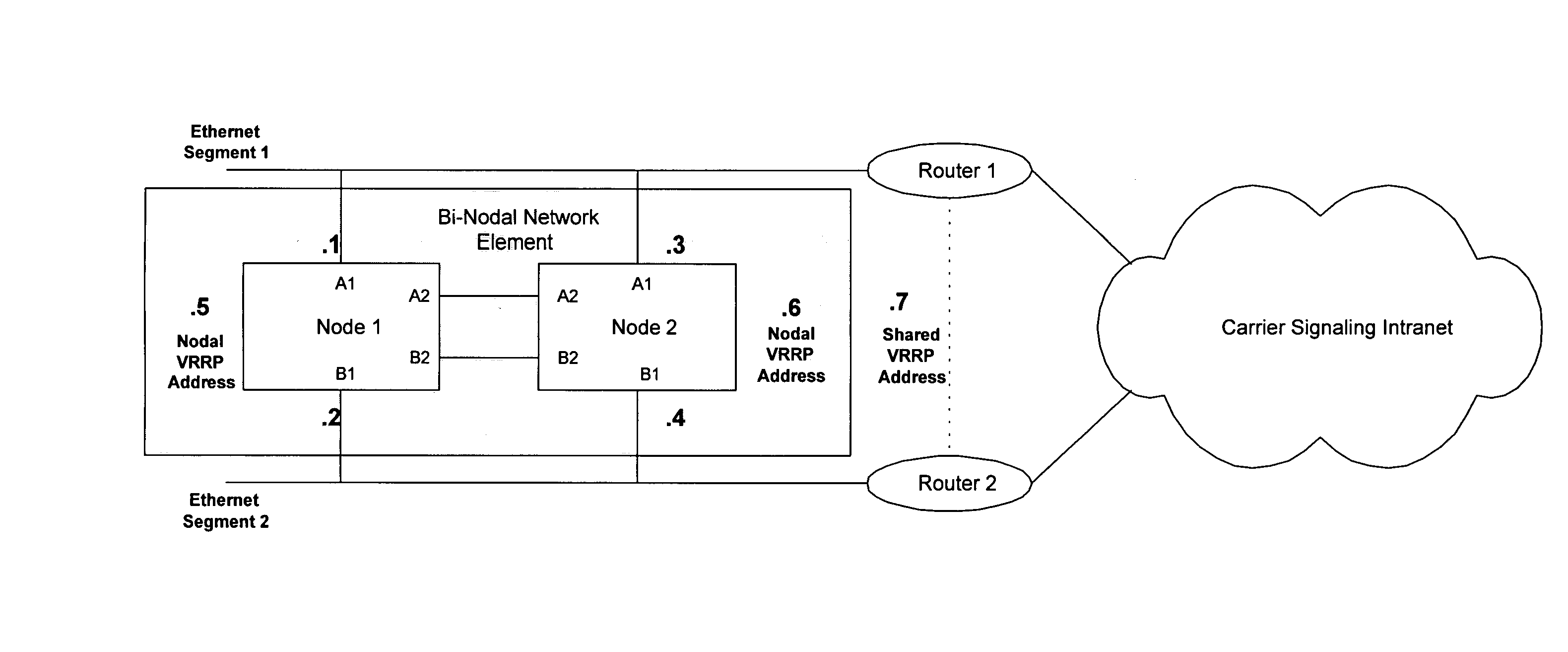
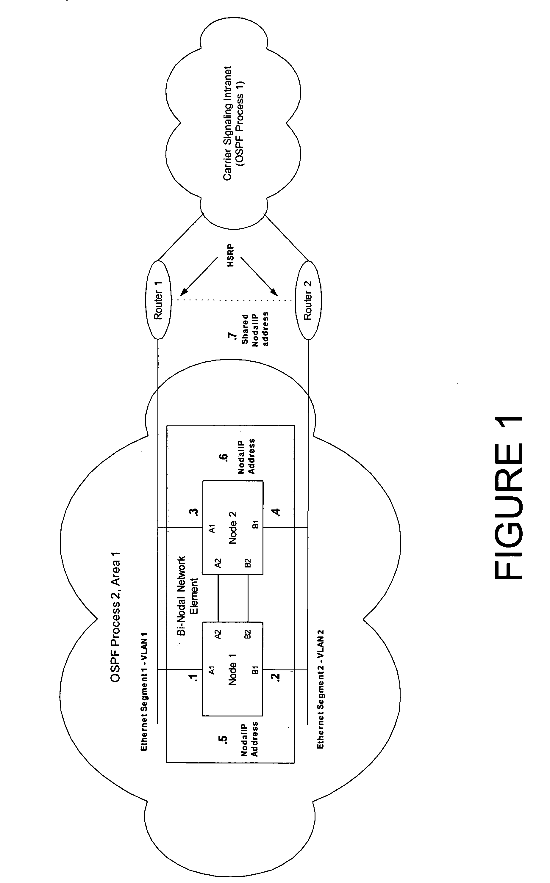
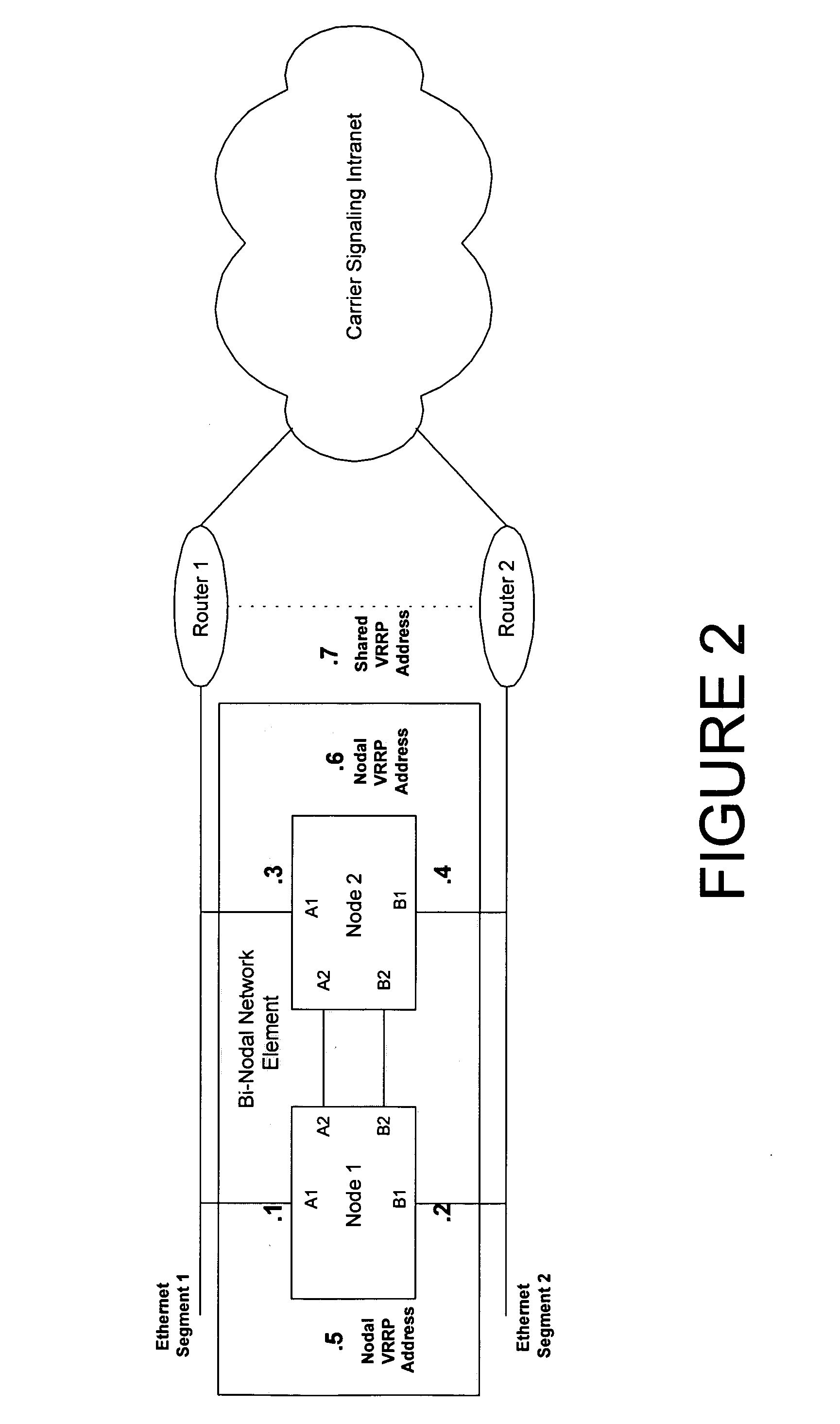
[0011]FIG. 1 illustrates an exemplary system in accordance with one embodiment of the present invention. The system includes a bi-nodal network element coupled to a carrier signaling intranet via a redundant router group utilizing OSPF. The bi-nodal network element includes two nodes, Node 1 and Node 2. The bi-nodal network element can be any type of network element, such as a dispatch communication processor (e.g., a highly available Dispatch Application Processor), integrated voice processing unit (iVPU) / transcoder, components of a base station controller, or the like.

[0012] The nodes can be arranged to provide redundancy and availability, such that one node is in an active state and the other node is in a standby state with internal node-to-node reachability via the A2 and B2 bi-nodal network element interfaces. This allows independent node failover across the carrier network for the case of individual node isolation due to multiple failure (e.g., failure of Node 1 interface A1 ...


PUM


Abstract

Systems and methods for communicating with bi-nodal network elements are provided. A single address is shared between both nodes of a bi-nodal network element. When packets are transmitted from either one of the nodes of the bi-nodal network element, the single address is employed as the source address of the packet. When packets are transmitted to either one of the nodes of the bi-nodal network element, the single address is employed as the destination address of the packet.

Description

[0001] The present application claims priority under 35 U.S.C. § 119 to U.S. Provisional Application No. 60 / 615,951, filed Oct. 6, 2004, the entire disclosure of which is herein expressly incorporated by reference.BACKGROUND OF THE INVENTION [0002] There are a variety of different types of communication networks. One type of communication network uses packets to communicate between various network elements. These packets include a header portion and a payload portion. The header portion includes, among other information, a destination address for the packet. Some packets also include a source address in the header portion of the packet identifying the network element that sent the packet. However, the arrangement of some networks requires changes to the source and destination addresses in packets. For example, due to the limited number of addresses available under Internet Protocol (IP), and to protect network elements that are coupled to the Internet through a private network, thes...

Claims


Application Information

Patent Timeline
IPC IPC(8): H04L12/56H04L12/28
CPCH04L12/66
Inventor QUICK, MATTHEW JOSEPH
Owner NEXTEL COMMUNICATIONS
Learn More