
Method and system of channel adaptation

a channel adaptation and channel technology, applied in the field of transmissions and retransmissions, can solve problems such as unfavorable, impossible, and delay problems in the structure of existing channels, and achieve the effects of avoiding the introduction of additional transport formats to be code multiplexed, if not impossible, and identifying existing channel structure delays

Inactive Publication Date: 2006-05-11
UNWIRED PLANET
View PDF7 Cites 51 Cited by
  • Summary
  • Abstract
  • Description
  • Claims
  • Application Information

AI Technical Summary

Benefits of technology

[0048] Consequently, it is an object of this invention to introduce a backward compatible channel structure allowing for shorter than existing transmission time intervals without PAR (peak-to-average power ratio) increase.

Problems solved by technology

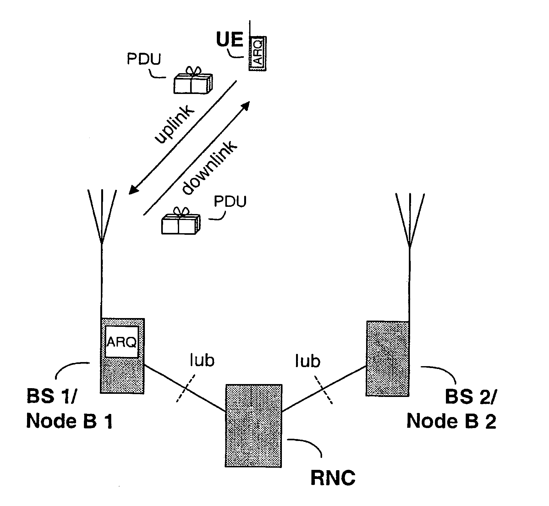
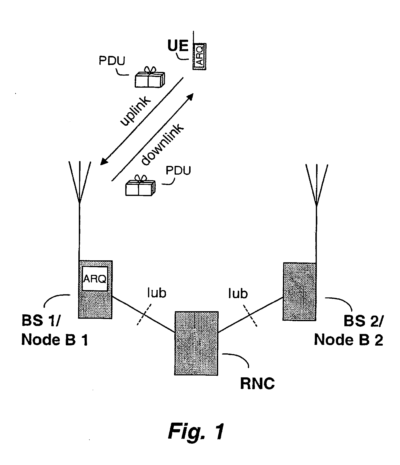
Delay problems have been identified for existing channel structure in some situations, e.g. communications according to TCP (Transmission Control Protocol), at high data rates, particularly in the uplink between UE and Node B.
Further, transmission power restrictions, particularly in uplink direction makes introduction of additional transport formats to be code multiplexed unfavorable, if not impossible.

Method used


Image

  • Method and system of channel adaptation
  • Method and system of channel adaptation
  • Method and system of channel adaptation

Examples


second embodiment

[0077] the sub-frame and radio frame decoding are non-exclusive. This is illustrated in FIG. 7 reflected in that condition > of FIG. 6 is excluded and step rf>> entered unconditionally when all sub-frames of a radio frame have been candidate decoded. The outcomes of decoding sub-frames and entire radio frame, respectively, are weighted and compared and the outcome (entire radio frame or one or more sub-frames) with greatest likelihood of being correct is selected in step >. One such comparison would be to select between whether or not a sub-frame channel structure is superimposed depending on, which of the alternatives would correspond to the smallest number of transmission errors. In FIG. 7, TTI comprising a plurality of radio frames does not include candidate(s) selection for more than first radio frame. However, more radio frames of TTI could be included at the expense of increased buffering. When a radio frame is TFCI detected only one radio frame (the first) of TTI is required...

third embodiment

[0078] a majority vote on the sub-frame decoding attempts of a received radio frame is determined prior to any decoding attempt of an entire radio frame. If, e.g., 3-5 out of 5 sub-frames are correctly decoded, transmissions are considered according to a sub-frame structure. Depending on false alarm rate and miss rate the vote threshold may be adjusted, e.g. requiring 4-5 correctly decoded sub-frames for considering data sent according to the sub-frame structure.

[0079] The preferred, second and third embodiments described above may be referred to as blind detection. However, it should be noted that according to the invention only TTI detection is blind. Once TTI is determined, TFCIrf and TFCIsf, respectively, is used to inform the receiver on control information, e.g. code rate.

[0080] On the transmitting side the terminal preferably decides whether or not to make use of the sub-frame channel structure according to needs and radio environment. The decision is based on one or more a...


PUM


Abstract

The present invention relates to transmissions and retransmissions in a communications system. It reveals a method and system for backward compatible detection of an introduced channel sub-frame structure particularly well suited for data transmissions. The invention is well suited for a cellular mobile radio communications system, particularly a Universal Mobile Telecommunications System, UMTS.

Description

TECHNICAL FIELD OF THE INVENTION [0001] The present invention relates to transmissions and retransmissions in a communications system, and more especially it relates to a cellular mobile radio system, particularly to a Universal Mobile Telecommunications System, UMTS or WCDMA system. BACKGROUND AND DESCRIPTION OF RELATED ART [0002] Transmission and retransmission of data to or from a mobile station, MS, or user equipment, UE, is previously known. It is also known to use medium access control and radio link control layers of a UMTS protocol structure in acknowledged mode for dedicated channels. [0003] In acknowledged mode, retransmissions are undertaken in case of detected transmission errors not recovered by forward error control. This is also called automatic repeat request, ARQ. With ARQ, retransmissions can be undertaken unless a transmitted message is (positively) acknowledged or if it is negatively acknowledged. Generally there are time limits for the respective positive and ne...

Claims


Application Information

Patent Timeline
Patent Type & Authority Applications(United States)
IPC IPC(8): H04J3/18H04J13/00H04L1/00H04L1/18H04W28/00H04W28/04H04W28/06H04W80/06
CPCH04L1/0006H04L1/0025H04L1/0038H04L1/0046H04L1/1819H04L1/1845
Inventor PARKVALL, STEFANDAHLMAN, ERIK
Owner UNWIRED PLANET
Learn More