Casing configuration for revolver cartridge loader

a cartridge loader and casing technology, applied in the field of casing configuration of revolver cartridge loaders, can solve the problems of difficult to quickly load fingers easily slip away from grasping the cylindrical casing, and inability to grasp the loader in a dark environment, so as to achieve quick loading of cartridges, quick alignment, and rapid release of cartridges into the cylinder

Inactive Publication Date: 2006-05-18
LIN JENN YUAN
View PDF12 Cites 14 Cited by
  • Summary
  • Abstract
  • Description
  • Claims
  • Application Information

AI Technical Summary

Benefits of technology

[0005] Accordingly, a primary objective of the present invention is to provide a casing configuration for revolver cartridge loader that allows fingers to manipulate and expedite effective grasping of a loader, and thereby allow achieving rapid loading of cartridges into the loader and quick alignment of the loader with a cylinder of a revolver, which thus effectuates rapid release of the cartridges into the cylinder.
[0011] Accordingly, fingers 50 can quickly grasp hold onto the successional arc-shaped grooves 32, which thereby enables rapid and convenient loading of cartridges 60 into a cylinder 70 (see FIG. 9).

Problems solved by technology

However, casings utilized for loading cartridges in such conventional art are of a cylindrical configuration, and are adopted with a smooth circumferential surface, and thus difficult for a user wanting to use their fingers to grasp hold of the loader in a dark environment, particularly in an emergency when the fingers will probably shake from nervousness.
In addition, should the fingers be stained with grease, the fingers will easily slip away from grasping hold of the cylindrical casing.
Furthermore, the hand holding the loader already loaded with cartridges easily misaligns the loader with a cylinder of the revolver, and is thus difficult to quickly load the cartridges into the cylinder.

Method used


Image

  • Casing configuration for revolver cartridge loader
  • Casing configuration for revolver cartridge loader
  • Casing configuration for revolver cartridge loader

Examples


Embodiment Construction

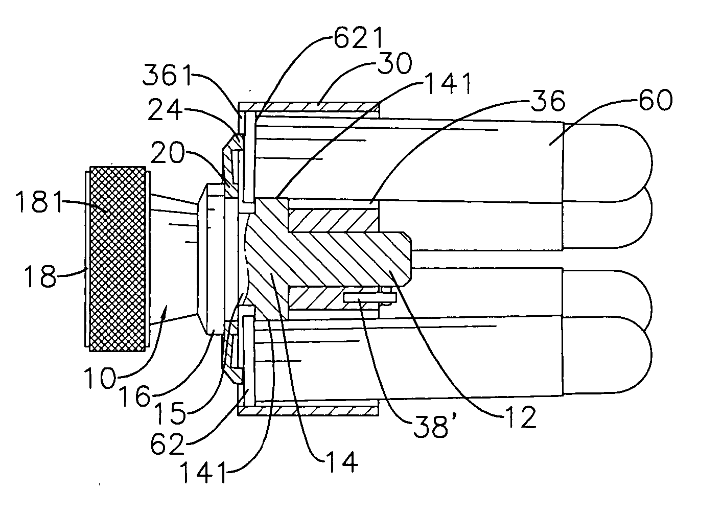
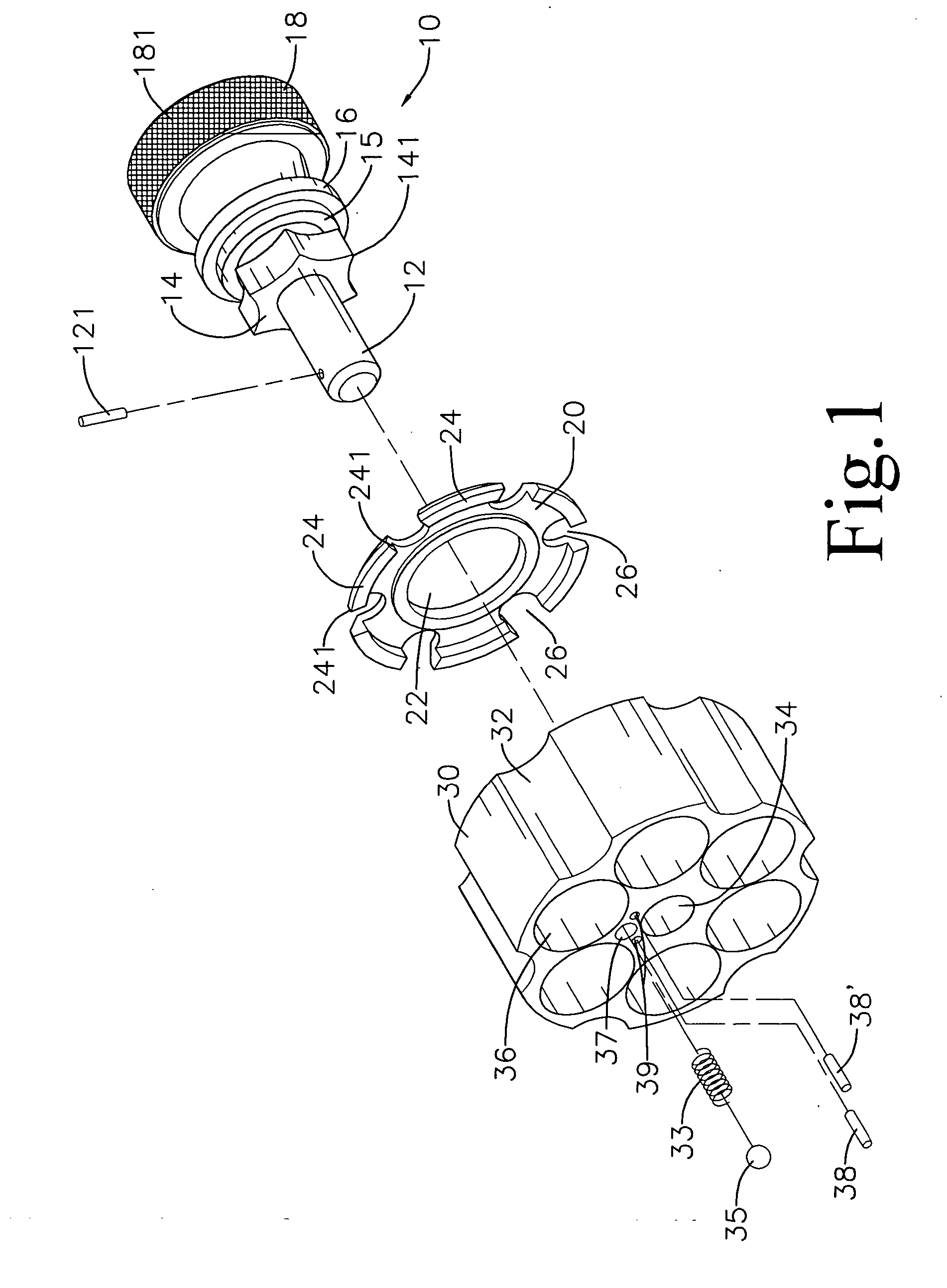
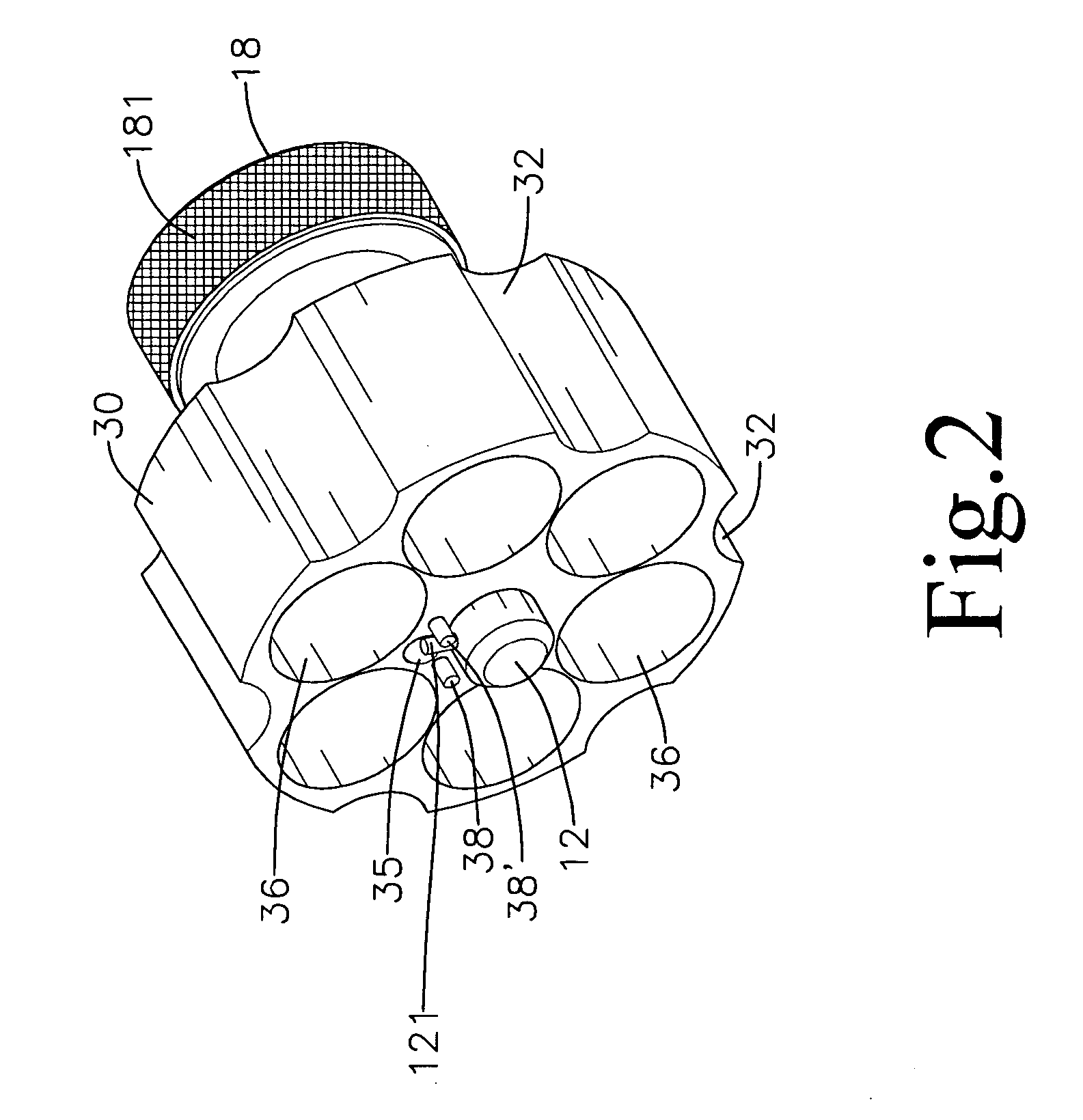
[0027] Referring to FIGS. 3, 6 and 7, which show a plurality of cartridges 60 respectively disposed in cartridge bores 36, at which time pointed protuberants 141 are respectively positioned between adjacent cartridge bores 36. A pin 121 is located between a ball bearing 35 and an inserting pin 38′, and thereby assumes a fixed position state, Fingers are used to rotate a circular ring 18, whereupon a shaft member 12, a pointed gear member 14, a small circular collar 15 and a large circular collar 16 rotate in synchronization. The pin 121 reverse displaces and depresses the ball bearing 35 downward, which thus recedes into a locating hole 37, thereby enabling the pin 121 to pass over the ball bearing 35 and position between the ball bearing 35 and an inserting pin 38, at which time the ball bearing 35 flips upward, and a side portion of the ball bearing 35 presses on the pin 121.

[0028] Referring to FIGS. 4 and 5, which show the pointed protuberants 141 respectively engaging an inner ...


PUM


Abstract

A casing configuration for revolver cartridge loader embodying a rotating shaft member; a packing member; a casing, an outer circumferential surface of which is configured with a plurality of successional arc-shaped grooves, and a shaft hole is defined central of the casing, moreover, a plurality of cartridge bores are equicicumferentially configured around the shaft hole. Configured side of the shaft hole is a locating hole, which provides for a spring and a ball bearing to be disposed thereinto, and two locating holes, which provide for two inserting pins to respectively penetrate thereinto and fix position. The shaft member is movably disposed within the shaft hole. The successional arc-shaped grooves thus allow for quickly grasping onto with fingers, thereby enabling rapid and convenient loading of cartridges into a cylinder of a revolver.

Description

BACKGROUND OF THE INVENTION [0001] (a) Field of the Invention [0002] The present invention relates to an improved casing configuration for revolver cartridge loader, and more particularly to the casing that advantages fingers of a user to grasp hold and thereby have contact control of the casing, which thus benefits the user to rapidly accomplish task of loading cartridges. [0003] (b) Description of the Prior Art [0004] Regarding conventional art of a loader for a revolver, U.S. Pat. No. 6,308,451 B1, U.S. Pat. No. 5,842,299, U.S. Pat. No. 4,313,275 and U.S. Pat. No. 4,202,124 all disclose loaders for use in revolvers. However, casings utilized for loading cartridges in such conventional art are of a cylindrical configuration, and are adopted with a smooth circumferential surface, and thus difficult for a user wanting to use their fingers to grasp hold of the loader in a dark environment, particularly in an emergency when the fingers will probably shake from nervousness. In addition...

Claims


Application Information

Patent Timeline
Patent Type & Authority Applications(United States)
IPC IPC(8): F41A9/61F41A9/82
CPCF41A9/85
Inventor LIN, JENN-YUAN
Owner LIN JENN YUAN
Why Eureka
Try Eureka