

Multifunctional multi-station rotary workbench
A rotary table, multi-station technology, applied in the direction of table, manufacturing tools, etc., can solve the problems of complex transmission structure, increased enterprise cost, long exchange time, etc., to save operators, improve efficiency, and low cost. Effect
- Summary
- Abstract
- Description
- Claims
- Application Information
AI Technical Summary
Problems solved by technology
Method used
Image

Examples
specific Embodiment approach 1
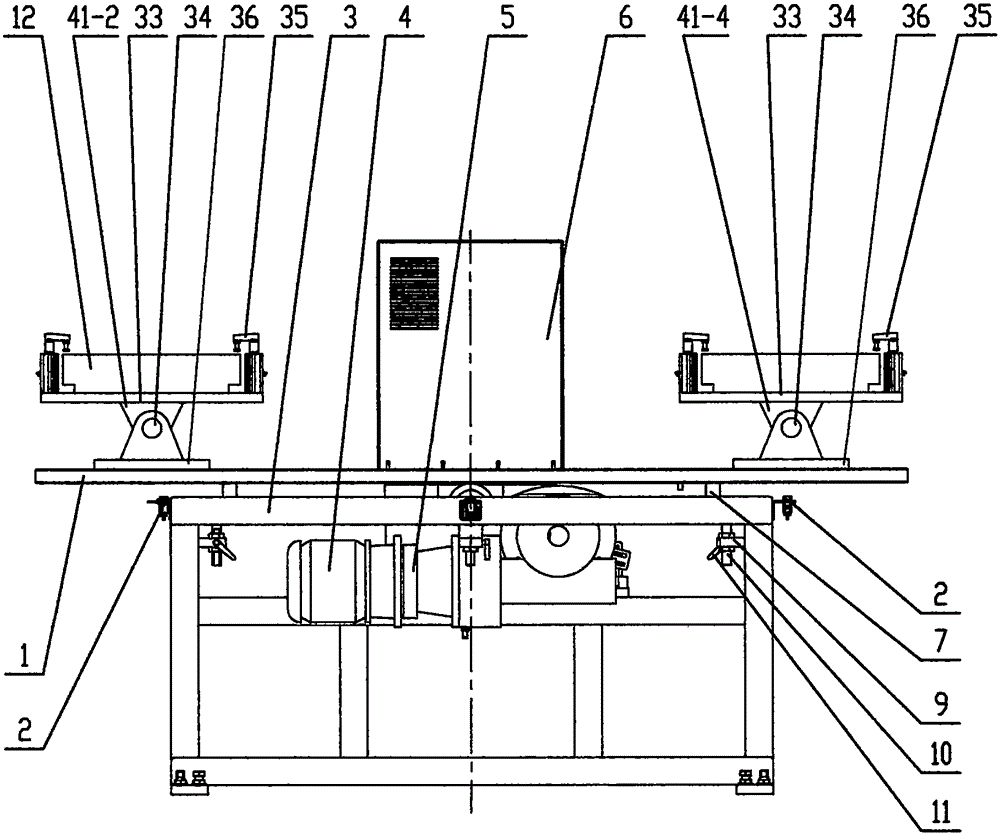
[0021] Specific implementation mode one: as Figure 1~4 As shown, a multi-functional multi-station rotary workbench that can swing or rotate the tooling fixture is characterized in that: a multi-functional multi-station rotary workbench includes a table top 1 and more than two sensors 2 (Fig. 4), frame 3, motor 4, reducer 5, rotating device 8, is characterized in that: also includes slip ring device 20, the first fixture 41-1, the second fixture 41-2, the third fixture Fixture 41-3 and fourth tooling fixture 41-4, automatic loading and unloading device, intelligent control system, the automatic loading and unloading device is arranged around the multifunctional and multi-station rotary workbench, the rotating device 8 is fixed on the frame 3, slides The ring device 20 is fixed on the table top 1 through the transition plate 21, and the table top 1 is fixed on the rotating shaft 38 of the rotating device 8, the first tooling fixture 41-1, the second tooling fixture 41-2, the th...
specific Embodiment approach 2
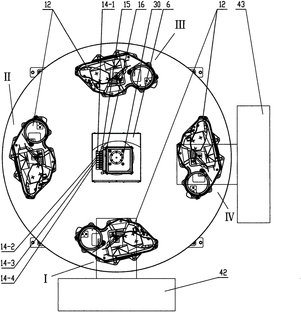
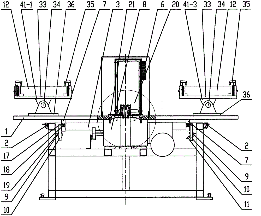
[0022] Specific implementation mode two: as Figure 1~4 As shown, the slip ring device 20 includes an air slip ring device and an electric slip ring 26, and the air slip ring device includes a housing 22, a bearing B23, a bearing C24, an air channel 27, a sealing ring 28, an annular channel 29, an air channel The nozzle D30, the gas nozzle E31, the fixed shaft 37, the lower transition plate 40, the fixed shaft A37, and the fixed shaft B39 of the rotating device 8 are connected concentrically, and the fixed shaft A37 is provided with a through hole 13 in the middle, and the flange and bearing of the electric slip ring 26 B23 and bearing C24 are concentrically installed on the fixed shaft 37, the motor 4 is connected with the reducer 5, the reducer 5 drives the rotation shaft 38 to rotate, the table top 1, the rotation shaft 38, the transition plate 21 and the casing 22 are coaxially installed and rotated synchronously; The source device 16 includes a solenoid valve A14-1, a sol...
specific Embodiment approach 3
[0024] Specific implementation mode three: as Figure 1~4As shown, the fixtures of the first fixture 41-1, the second fixture 41-2, the third fixture 41-3 and the fourth fixture 41-4 all include a fixed plate B33, a rotating shaft 34, and two Above rotary clamp cylinder 35, base 36, base 36 is fixed on the table top 1, base 36 and fixed plate B33 are connected with rotating shaft 34, fixed plate B33 can rotate or swing around rotating shaft 34, rotating shaft 34 is connected with power source, and power source is Motor or swing cylinder, the workpiece 12 is fixed on the fixed plate B33 and clamped by the rotary clamping cylinder 35, the number of solenoid valve A14-1, solenoid valve B14-2, solenoid valve C14-3, solenoid valve D14-4 is greater than or equal to The number of fixtures, solenoid valve A14-1, solenoid valve B14-2, solenoid valve C14-3, solenoid valve D14-4 open or close compressed air, respectively control the first fixture 41-1, the second fixture 41- 2. Clamping...
PUM
 Abstract
Description
Claims
Application Information