Combustor flow sleeve with optimized cooling and airflow distribution

a technology of turbine engines and flow sleeves, applied in the direction of machines/engines, mechanical equipment, light and heating equipment, etc., can solve the problems of reducing the efficiency and power of the turbine, increasing the system pressure drop, and reducing the cooling efficiency of the flow

Active Publication Date: 2006-05-18
SIEMENS ENERGY INC
View PDF46 Cites 40 Cited by
  • Summary
  • Abstract
  • Description
  • Claims
  • Application Information

AI Technical Summary

Benefits of technology

[0008] A plurality of openings are provided about the flow sleeve in a region defined between the axial downstream end of the sleeve and an axially central location of the flow sleeve inclusive. In one embodiment, the plurality of openings can be located in an axially central region of the flow sleeve. The plurality of opening can help to make an uneven distribution of the flow into the head-end through the passage substantially uniform.

Problems solved by technology

One consequence of such unnecessary cooling is an increase in system pressure drop, which in turn lowers the efficiency and power of the turbine.
These uneven flow distributions can diminish the cooling effectiveness of the flow.
In addition, such flow imbalances can lead to a decrease in combustor performance including the production of undesired nitrides of oxygen (NOx).

Method used


Image

  • Combustor flow sleeve with optimized cooling and airflow distribution
  • Combustor flow sleeve with optimized cooling and airflow distribution
  • Combustor flow sleeve with optimized cooling and airflow distribution

Examples


Embodiment Construction

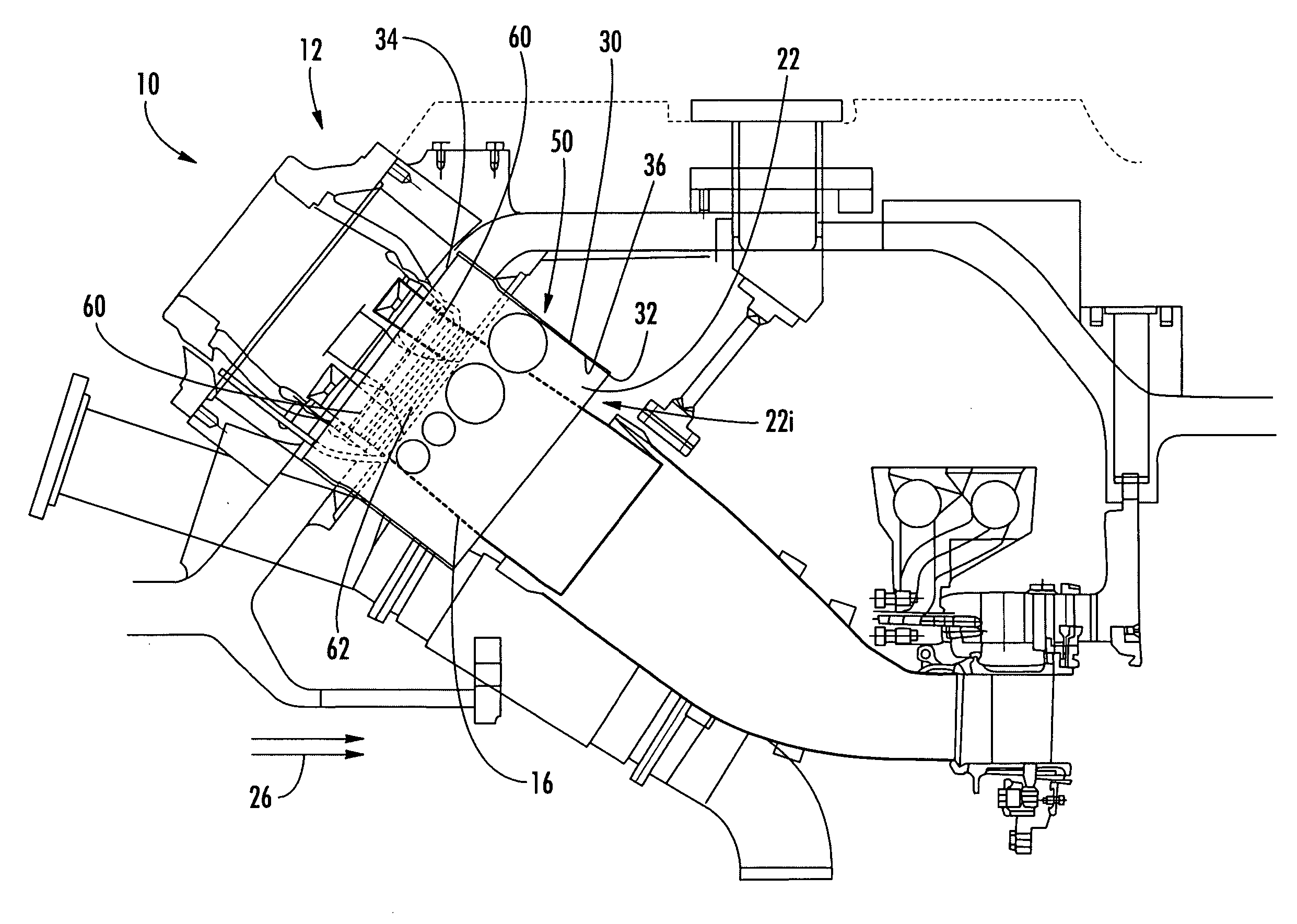
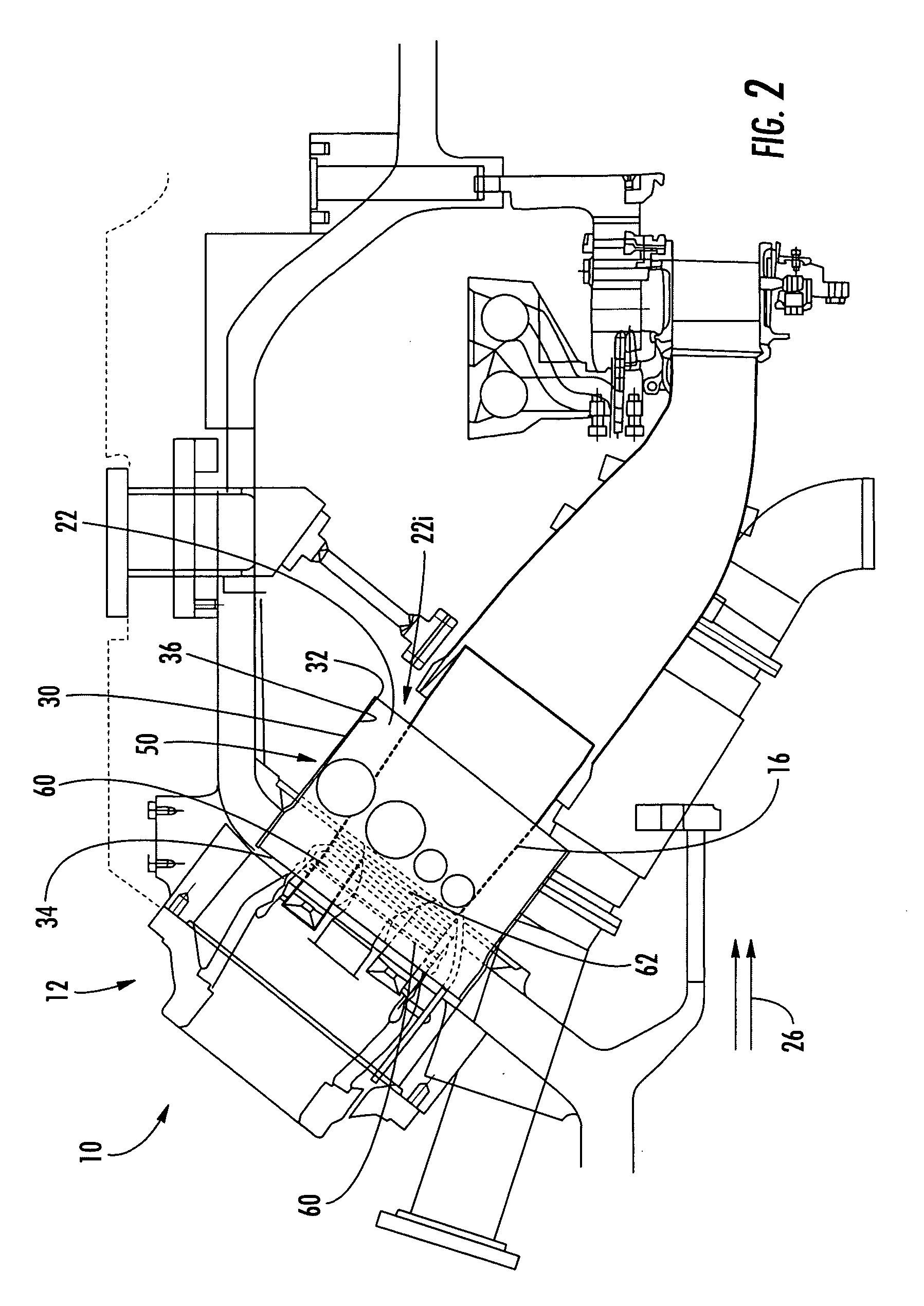
[0017] Embodiments of the present invention address the uneven flow distribution and unnecessary cooling associated with prior combustor flow sleeves. According to embodiments of the invention, a combustor flow sleeve can be configured to provide more targeted cooling while making the flow into the combustor head-end more uniform. Embodiments of the invention will be explained in the context of one possible system, but the detailed description is intended only as exemplary. Embodiments of the invention are shown in FIGS. 2-4, but the present invention is not limited to the illustrated structure or application.

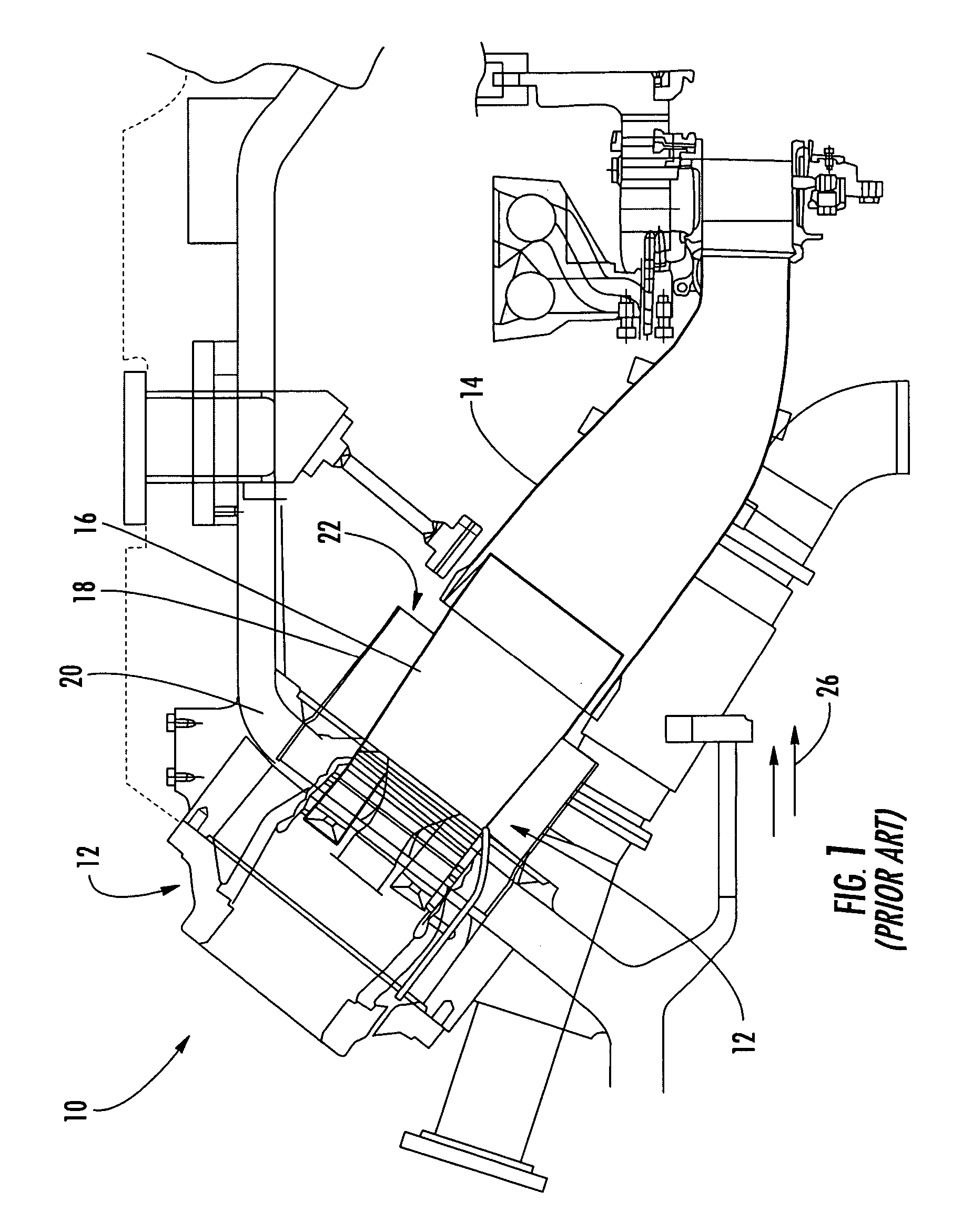
[0018] As mentioned earlier, various flow sleeves are known in the art, and embodiments of the invention are not limited to any specific flow sleeve. A flow sleeve 30 can be generally tubular having an axial upstream end 32 and an axial downstream end 34. The terms “upstream” and “downstream” are used to refer to the ends of the flow sleeve 30 relative to the direction of airf...


PUM


Abstract

Embodiments of the invention relate to a combustor flow sleeve for a turbine engine. The flow sleeve can be configured to optimize cooling and airflow distribution. The flow sleeve can include first and second sets of openings. A first set of openings can be provided for impingement cooling the areas of the liner that are subjected to high thermal loads. The second set of openings can be provided to more evenly distribute the airflow into the combustor head-end. By focusing the cooling on the areas of need and by making the airflow more uniform, embodiments of the invention can reduce the system pressure drop and enhance the performance and power of the engine.

Description

FIELD OF THE INVENTION [0001] The invention relates in general to turbines engines and, more specifically, to combustor flow sleeves for turbine engines. BACKGROUND OF THE INVENTION [0002]FIG. 1 shows one known combustor system 10 of a turbine engine. The combustor 10 includes a head-end 12, a transition 14, and a liner 16 extending therebetween. The term “combustor head-end” generally refers to the fuel injection / fuel-air premixing portion of the combustor 10. The specific components and geometry in the area of the head-end 12 can vary from combustor to combustor. The liner 16 extends from the combustor head-end 12 and toward the transition 14. The liner 16 can connect between the combustor head-end 12 and the transition 14 in any of a number of ways, as is known in the art. [0003] The liner 16 requires cooling because of the high temperatures of the combustion occurring inside of the liner. At least a portion of the liner can be cooled by air. One known scheme for air-cooling the ...

Claims


Application Information

Patent Timeline
Patent Type & Authority Applications(United States)
IPC IPC(8): F23R3/04
CPCF05B2260/201F23R3/04F23R3/26
Inventor BLAND, ROBERT J.
Owner SIEMENS ENERGY INC
Why Eureka
Try Eureka