Hydraulic ride control system for working vehicle

a technology of hydraulic control system and working vehicle, which is applied in the direction of fluid couplings, clutches, constructions, etc., can solve the problems of shaken body of the working vehicle and inability to fully absorb conventional techniques, and achieve the effect of improving vibration suppression performan

Active Publication Date: 2006-05-18
NIHON KENKI CO LTD
View PDF6 Cites 20 Cited by
  • Summary
  • Abstract
  • Description
  • Claims
  • Application Information

AI Technical Summary

Benefits of technology

[0017] As the present invention can variably control the opening of the opening control valve by the control means depending on the weight of the front section, vibrations which take place when travelling with a loa

Problems solved by technology

When traveling with the load, up and down movements of the vehicle cause a boom to swing up and down due to an increased weight of the bucket, and as a result, amplify vibrations of the vehicle.
When the opening is conversely too large relative to the weight of the front section, the vibrations of the front sec

Method used


Image

  • Hydraulic ride control system for working vehicle
  • Hydraulic ride control system for working vehicle
  • Hydraulic ride control system for working vehicle

Examples


first embodiment

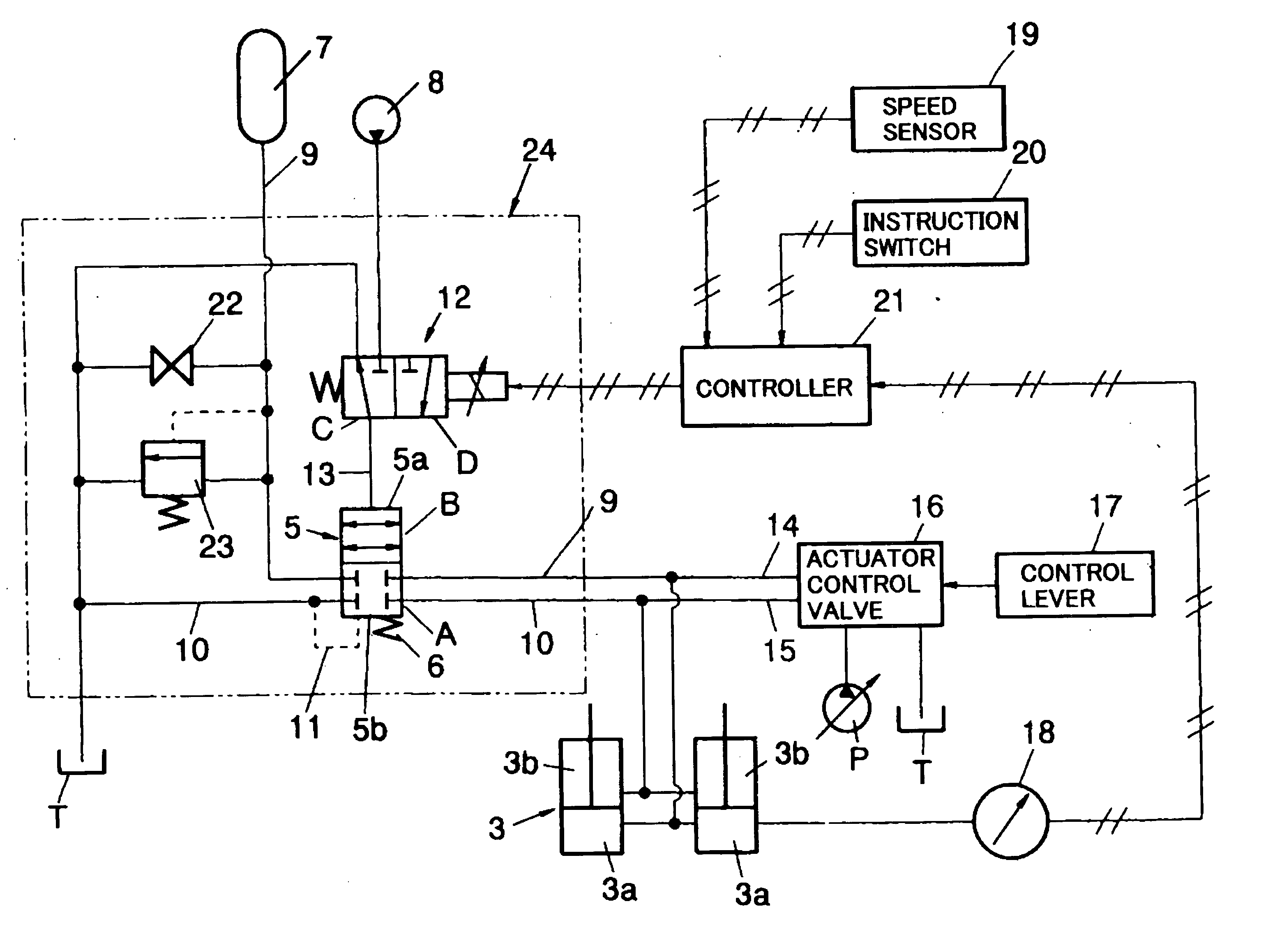
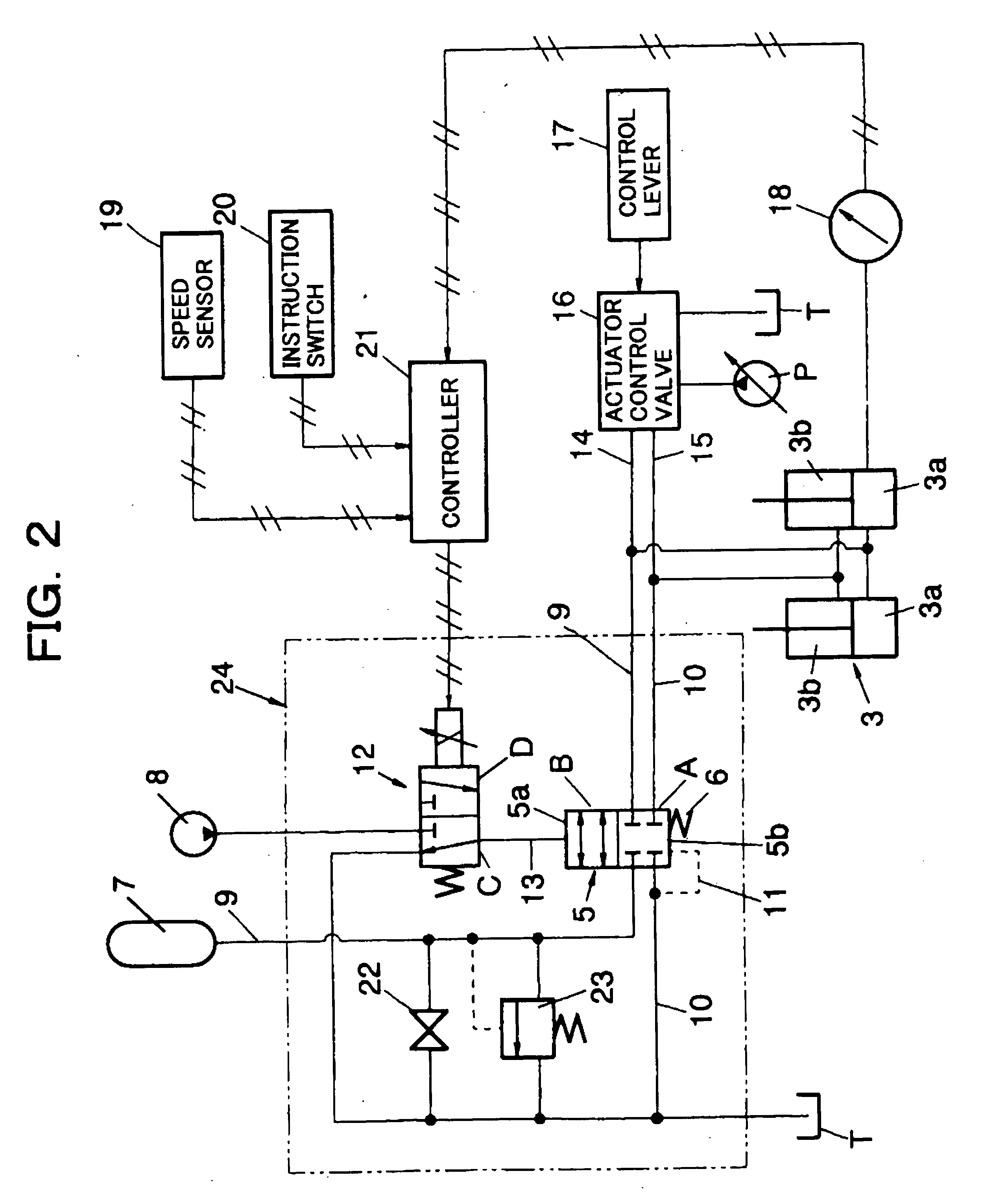
[0029] Referring next to FIG. 2, the hydraulic ride control system according to the second embodiment has a branch circuit 24 branched out from a main circuit for driving the boom cylinder 3. Bottom pressure chambers 3a and rod pressure chambers 3b of the boom cylinders 3 are connected to an actuator control valve 16 via main lines 14 and 15, respectively. The actuator control valve 16 bleeds a pressure from a hydraulic pump P to ones of the bottom pressure chambers 3a and rod pressure chambers 3b of the boom cylinders 3 in accordance with a control stroke of a control lever 17, or brings the other pressure chambers into communication with a reservoir T. As a result, the boom cylinders 3 extend or retract.

[0030] The branch circuit 24 is equipped with branch lines 9 and 10, which are branching out from the main lines 14 and 15, respectively, and are connectable to an accumulator 7 and the reservoir T, respectively, via an opening control valve 5. It is to be noted that the branch li...

second embodiment

[0046] In the above-described first embodiment, the pressure of the accumulator 7 when the opening control valve 5 is in the closed position A is substantially equal to the pressure in the bottom pressure chambers 3a of the boom cylinder 3 when the opening control valve 5 was in the open position B shortly before its switching into the closed position A. The load pressure on the boom cylinders 3, however, frequently varies depending on the weight of the load, the holding angle of the boom 1, and the like. At the moment that the opening control valve 5 has been switched into the open position B, there is accordingly a difference in pressure between the bottom pressure chambers 3a of the boom cylinders 3 and the accumulator 7. Due to this pressure difference, an undesired motion such as sudden lowering of the boom 1 and as a result, a shock may take place to deleteriously affect the riding comfort.

[0047] With reference to the circuit diagram shown in FIG. 8, the hydraulic ride contro...


PUM


Abstract

A hydraulic ride control system for a working vehicle such as a wheel loader is provided with boom cylinders, an actuator control valve for controlling a pressure in bottom pressure chambers of the boom cylinders, an accumulator connected to the bottom pressure chambers of the boom cylinders via a connection line, an opening control valve having a pilot chamber to selectively communicating or cutting off the connection line depending on a pressure in the pilot chamber, and a selector unit for selectively feeding a pressure to or draining a pressure from the pilot chamber. The selector unit comprises a controller for variably controlling an opening of the opening control valve.

Description

FIELD OF THE INVENTION [0001] This invention relates to a hydraulic ride control system for a working vehicle such as a wheel loader. DESCRIPTION OF THE BACKGROUND [0002] In digging / loading work by a wheel loader, earth, sand or the like loaded in a bucket is often moved to a predetermined place. When traveling with the load, up and down movements of the vehicle cause a boom to swing up and down due to an increased weight of the bucket, and as a result, amplify vibrations of the vehicle. [0003] With a view to suppressing these vibrations, a bottom pressure chamber of a boom cylinder and an accumulator are brought into communication with each other during traveling to have pressure fluctuations in the bottom pressure chamber absorbed in the accumulator, and during digging work with a bucket, on the other hand, the communication with the accumulator is cut off to prevent the absorption of digging force in the accumulator. As a conventional technique of this sort, reference can be made...

Claims


Application Information

Patent Timeline
IPC IPC(8): F16D31/02
CPCE02F9/2207
Inventor KOBAYASHI, YOSHINOBUMATSUZAKI, HIROSHIUENO, KATSUMI
Owner NIHON KENKI CO LTD
Why Eureka
Try Eureka