Active filter element for end face incident flow

a technology of filter element and incident flow, which is applied in the direction of separation process, filtration separation, transportation and packaging, etc., can solve the problems of requiring a lot of space, needing a permanent bond between the carrier material and the gas stream, and lack of a means to filter out solid particles

Inactive Publication Date: 2006-05-18
MANN HUMMEL GMBH
View PDF16 Cites 49 Cited by
  • Summary
  • Abstract
  • Description
  • Claims
  • Application Information

AI Technical Summary

Benefits of technology

[0023] In accordance with yet another advantageous embodiment of the invention, the adsorbent particles are spherical activated carbon particles, which offer the advantage that their active surface is very large.
[0024] Preferably, the ad

Problems solved by technology

Here, too, however, the drawback is the need for a permanent bond between the carrier material and the adsorbent particles and the lack of a means to filter solid particles out of t

Method used


Image

  • Active filter element for end face incident flow
  • Active filter element for end face incident flow

Examples


Embodiment Construction

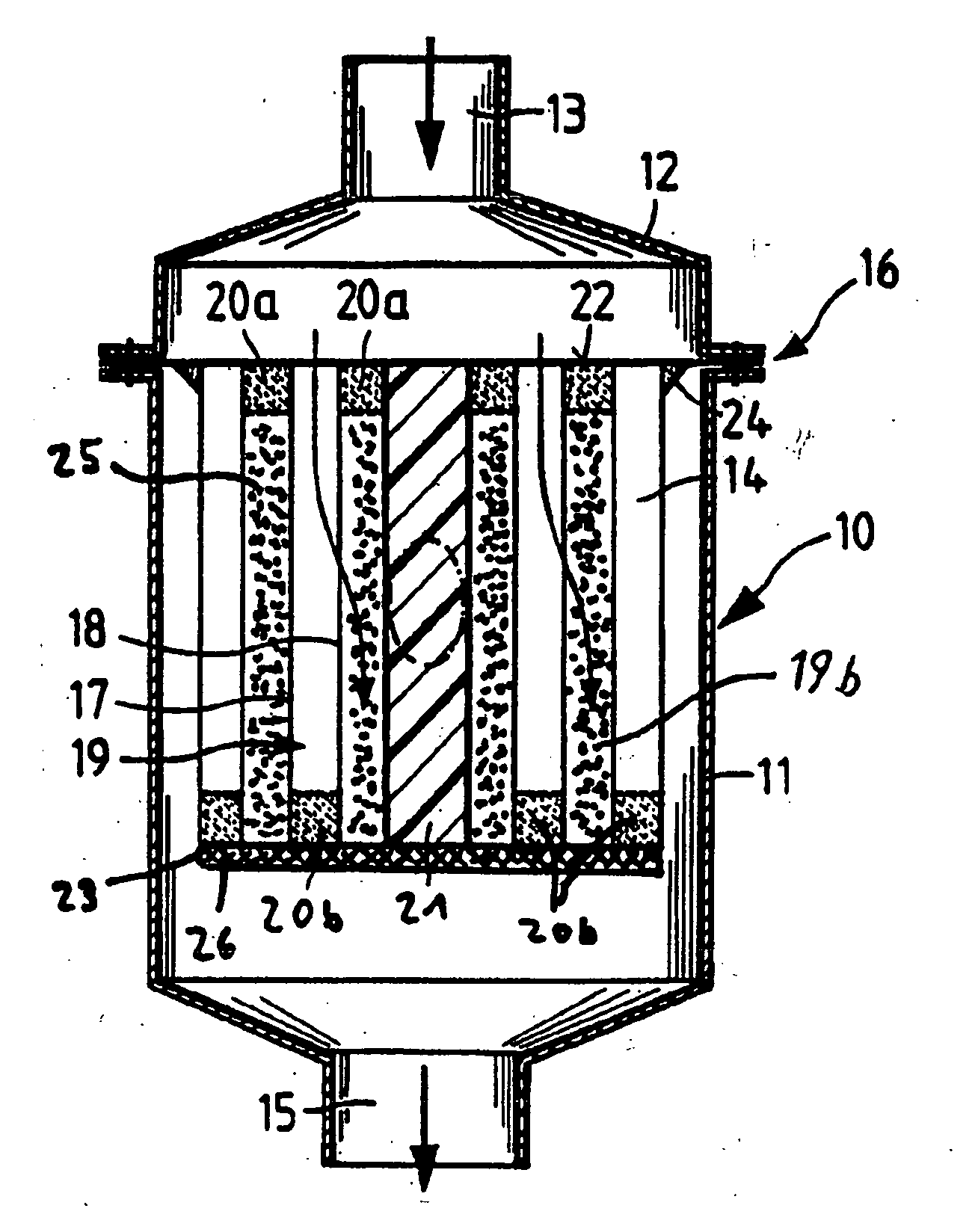
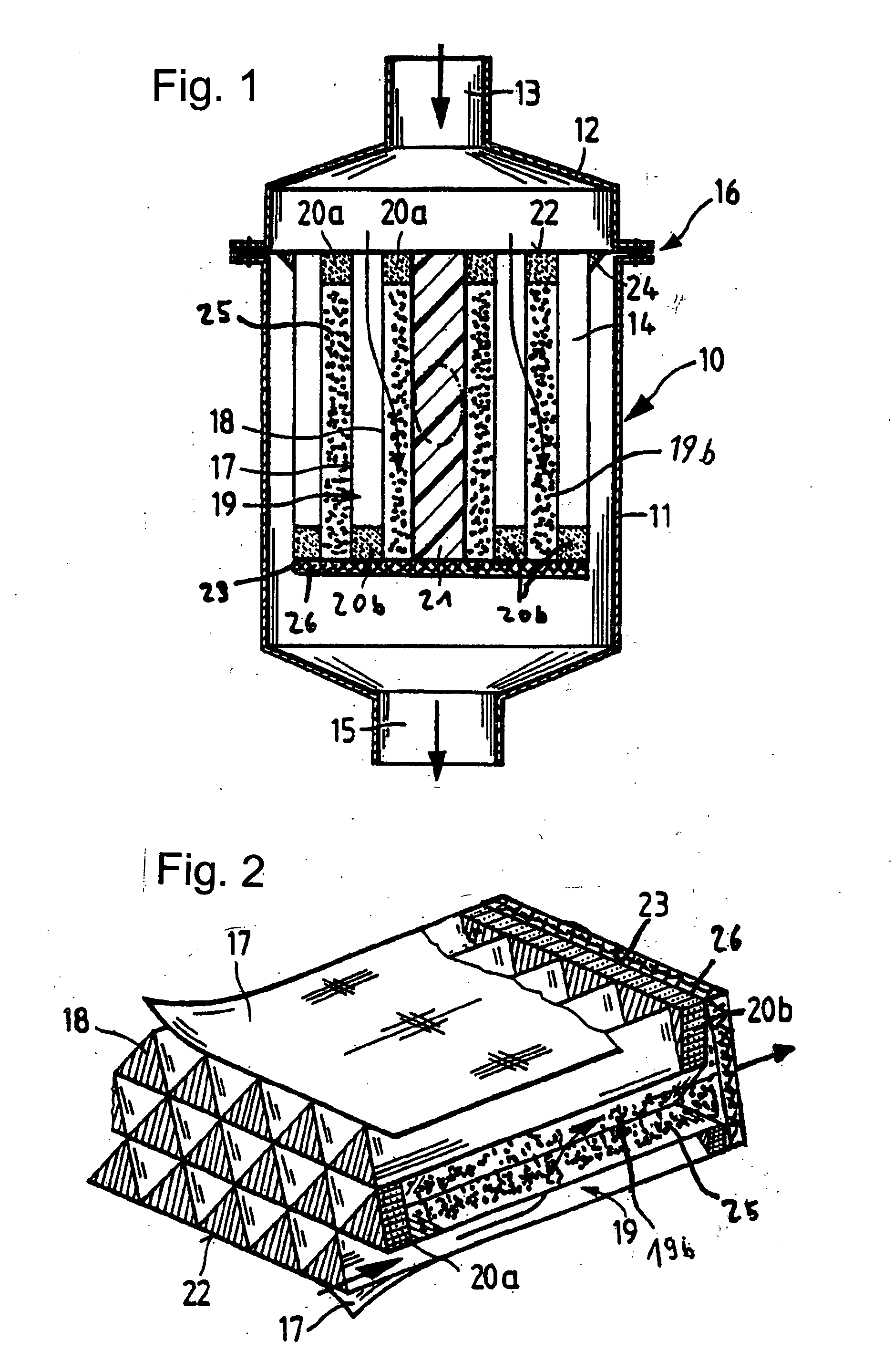
[0031] An inline filter according to FIG. 1 has a housing 10 with a housing cup 11 and a lid 12. The lid has an inlet 13 through which the fluid to be filtered flows into the housing to enter a filter cartridge 14 and then flows out through an outlet 15 as indicated by the arrows. The filter cartridge 14 is fixed in a parting line 16 of the housing. Filter cartridge 14 is configured as a wound filter cartridge and is depicted schematically. Different layers 17, 18 form channels 19 through which the fluid to be filtered flows. The channels are alternately sealed by seals 20a, 20b, such that the fluid to be filtered must change channels as it flows through the filter cartridge 14. This causes the fluid to be filtered. The layers 17, 18 are furthermore sealingly wound around a core 21 which may, for example, have an oval cross section.

[0032] To produce a reliable separation between an incident flow side 22 and an discharge side 23, the filter cartridge is held in a filter frame 24. Th...


PUM

PropertyMeasurementUnit
Shapeaaaaaaaaaa
Permeabilityaaaaaaaaaa

Abstract

A filter element formed from at least one flat layer of permeable filter medium alternating with at least one pleated layer in such a way that the resulting channels have an open, especially triangular, cross section, a first group of channels being tightly sealed at one end and a second group of channels being tightly sealed at the other end such that a fluid to be filtered flowing through the filter element from an incident flow side formed by one end face to a discharge side formed by the opposite end face, must pass through one of the layers, a seal for sealing the incident flow side from the discharge side of the filter element at an installation site, and each side of each channel of the first group which is spaced from the periphery of the filter element is bordered by a channel of the second group such that fluid can flow through the full area of the channels except for fold edges, and at least one group of channels is filled with adsorbent particles and closed by a gas-permeable fabric disposed over the corresponding end face of the filter element, the fabric pores being smaller than the adsorbent particles.

Description

BACKGROUND OF THE INVENTION [0001] The invention relates to a filter element for end face incident flow in accordance with the species of claim 1. The invention further relates to a filter in which the described filter element is installed and to a method for producing a filter element of the foregoing type. [0002] The passenger compartment filters currently used to adsorb harmful gases are flat filter elements consisting of highly porous plastic foams with activated carbon bonded thereto or several superimposed bonded activated carbon media. Also used are flat filter elements pleated in zigzag fashion with an activated carbon layer bonded to the filter medium. [0003] Published European patent application no. EP 383,236 discloses a filter device with a flat carrier that is pleated in zigzag fashion. The flat carrier is gas permeable, since the gaseous medium to be filtered must penetrate the flat carrier. The adsorbent particles must be permanently bonded to the carrier material usi...

Claims


Application Information

Patent Timeline
IPC IPC(8): B01D53/02
CPCB01D46/0036B01D46/525B01D53/0415B01D2253/102B01D2253/304B01D2253/308B01D2253/342B01D2257/702B01D2257/90B01D2259/4516B01D2259/4566B01D2271/02
Inventor STEINS, OLIVER
Owner MANN HUMMEL GMBH
Why Eureka
Try Eureka