
Driving device and optical device using the same

a technology of optical devices and driving devices, applied in piezoelectric/electrostrictive/magnetostrictive devices, mountings, instruments, etc., can solve problems such as the inability to drive stable, and achieve the effect of small overall length

Active Publication Date: 2006-05-18
KONICA MINOLTA OPTO
View PDF3 Cites 22 Cited by
  • Summary
  • Abstract
  • Description
  • Claims
  • Application Information

AI Technical Summary

Benefits of technology

"The present invention provides a driving device with a small overall length and a compact-type optical device. The driving device includes an electromechanical transducer, a driving frictional member, and a moving body which can frictionally engage with the driving frictional member. The moving body has frictional surfaces with a length greater than the distance by which it is movable. The driving device is suitable for driving image pickup units such as cameras, pickups of disk devices, and miniaturized optical systems such as endoscopes. The invention is easy to use and provides efficient driving for image pickup units."

Problems solved by technology

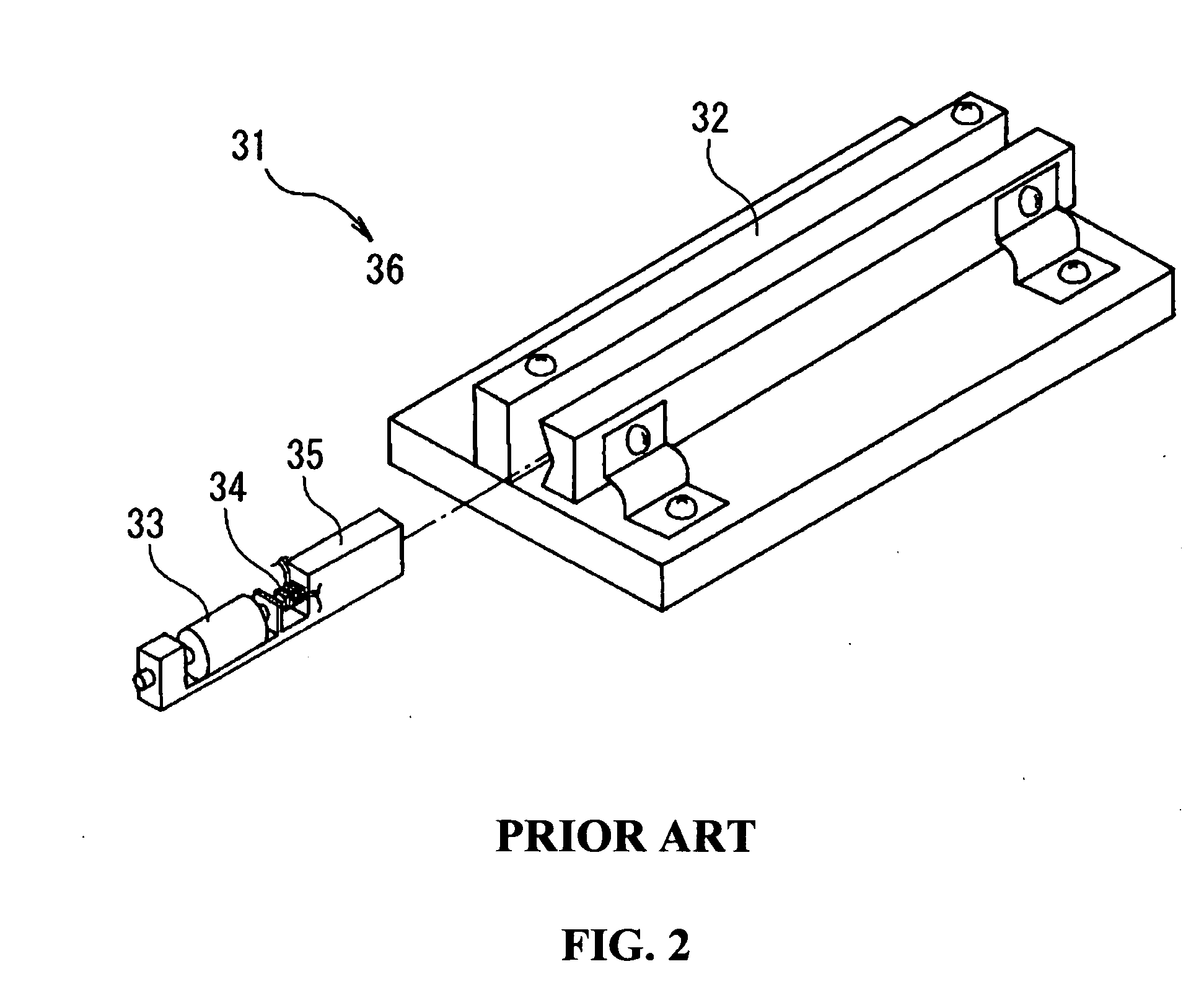
In the case of realizing a significantly-small-sized free-running driving device 31, if the wiring is provided using a common flexible substrate, this can not provide sufficient flexibility, which hinders the movement of the moving body 35, thus inducing the problem of impossibility of stable driving.

Method used


Image

  • Driving device and optical device using the same
  • Driving device and optical device using the same
  • Driving device and optical device using the same

Examples


Embodiment Construction

[0030] Hereinafter, embodiments of the present invention will be described with reference to the drawings.

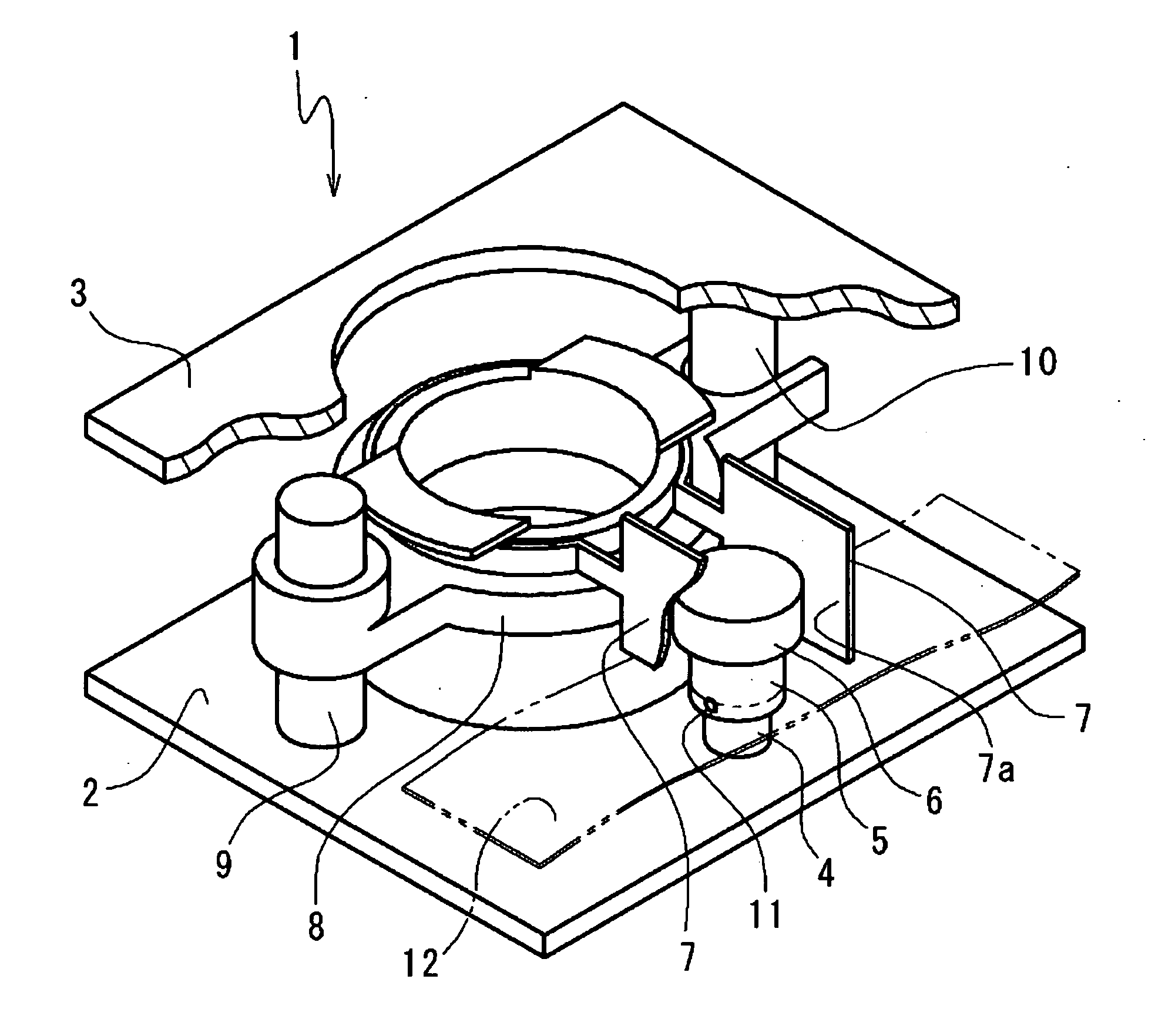
[0031]FIG. 4 illustrates a driving device 1 according to a first embodiment of the present invention. The driving device 1 is configured between a first frame 2 and a second frame 3. The driving device 1 is constituted by a stationary body 4 which is a cylindrical-shaped weight, an electromechanical transducer 5 which is secured to the upper portion of the stationary body 4 and formed from a cylindrical-shaped piezoelectric device with a diameter greater than that of the stationary body 4, a driving frictional member 5 which is secured to the upper end of electromechanical transducer 5 and is made of a ceramic material having a diameter greater than that of the electromechanical transducer 5, a moving body 7 which is formed from a metal spring and engaged with the driving frictional member 6 at their opposing frictional surfaces 7a sandwiching the driving frictional member 6 th...


PUM


Abstract

A driving device according to the present invention includes an electromechanical transducer secured at its one end to a stationary body, a driving frictional member secured to the other end of the electromechanical transducer, and a moving body which frictionally engage with the driving frictional member. The moving body has a length smaller than the total length of the stationary body, the electromechanical transducer 5 and the driving frictional member. The moving body moves such that it extends beyond the lengthwise end portions of the driving frictional member.

Description

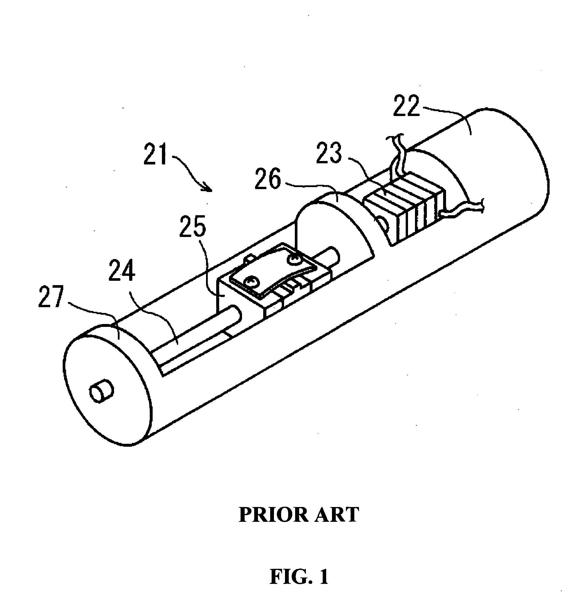
[0001] The present application claims priority to Japanese Patent Application No. 2004-328375 filed on Nov. 12, 2004, the entire content of which is hereby incorporated by reference. BACKGROUND OF THE INVENTION [0002] 1. Field of the Invention [0003] The present invention relates to a driving device using an electromechanical transducer. Further, the present invention relates to an optical device for driving an optical component (a lens or the like) using the driving device. [0004] 2. Description of the Related Art [0005] As described in JP-A No. 2001-60113, there have been well known driving devices of device-fixing types and free-running types, as driving devices utilizing electromechanical transducers. As illustrated in FIG. 1, a conventional device-fixing type driving device 21 is constituted by an electromechanical transducer (piezoelectric device) 23 secured to a stationary body 22 at its one end, a driving frictional member 24 secured to the other end of the electromechanical...

Claims


Application Information

Patent Timeline
Patent Type & Authority Applications(United States)
IPC IPC(8): H02N2/00H10N30/00
CPCG02B7/005H02N2/025
Inventor OKAMOTO, YASUHIRO
Owner KONICA MINOLTA OPTO
Learn More