View angle controlling sheet and liquid crystal display apparatus using the same

Inactive Publication Date: 2006-05-18
DAI NIPPON PRINTING CO LTD
View PDF25 Cites 58 Cited by
  • Summary
  • Abstract
  • Description
  • Claims
  • Application Information

AI Technical Summary

Benefits of technology

[0028] According to the view angle controlling sheet of the present invention, since the lens parts having a trapezoidal cross sectional shape made of a light transmissible resin are arranged by a predetermined interval, the cross sectional shape of the adjacent lens parts is wedge like with the lower bottom surface wider to the light source side as substantially isosceles trapezoidal, substantially isosceles triangular, trapezoidal unsymmetrical in the right and left direction or acute triangular unsymmetrical in the right and left direction, and the wedge part is filled with a material having the light absorbing property, a view angle controlling sheet having the view angle controlling effect can be obtained. Moreover, since the view angle controlling sheet of the present invention is provided between the light source and the liquid crystal panel of a liquid crystal display apparatus, the light incident angle

Problems solved by technology

On the other hand, in the case of working in a commuter train or according to a liquid crystal display installed at a public place such as an ATM, it is inconvenient to have the screen peeped from the other people.
However, according to the conventional louver type view angle controlling sheet, since it has a configuration of merely forming the colored layer and the transparent layer alternately with a rectangular louver cross sectional shape so as to merely absorbing the light beam from the oblique direction by the colored layer without obtaining the converging effect of converging the light beam from the light source to a targeted output angle with a large light amount loss and a low

Method used


Image

  • View angle controlling sheet and liquid crystal display apparatus using the same
  • View angle controlling sheet and liquid crystal display apparatus using the same
  • View angle controlling sheet and liquid crystal display apparatus using the same

Examples


first embodiment

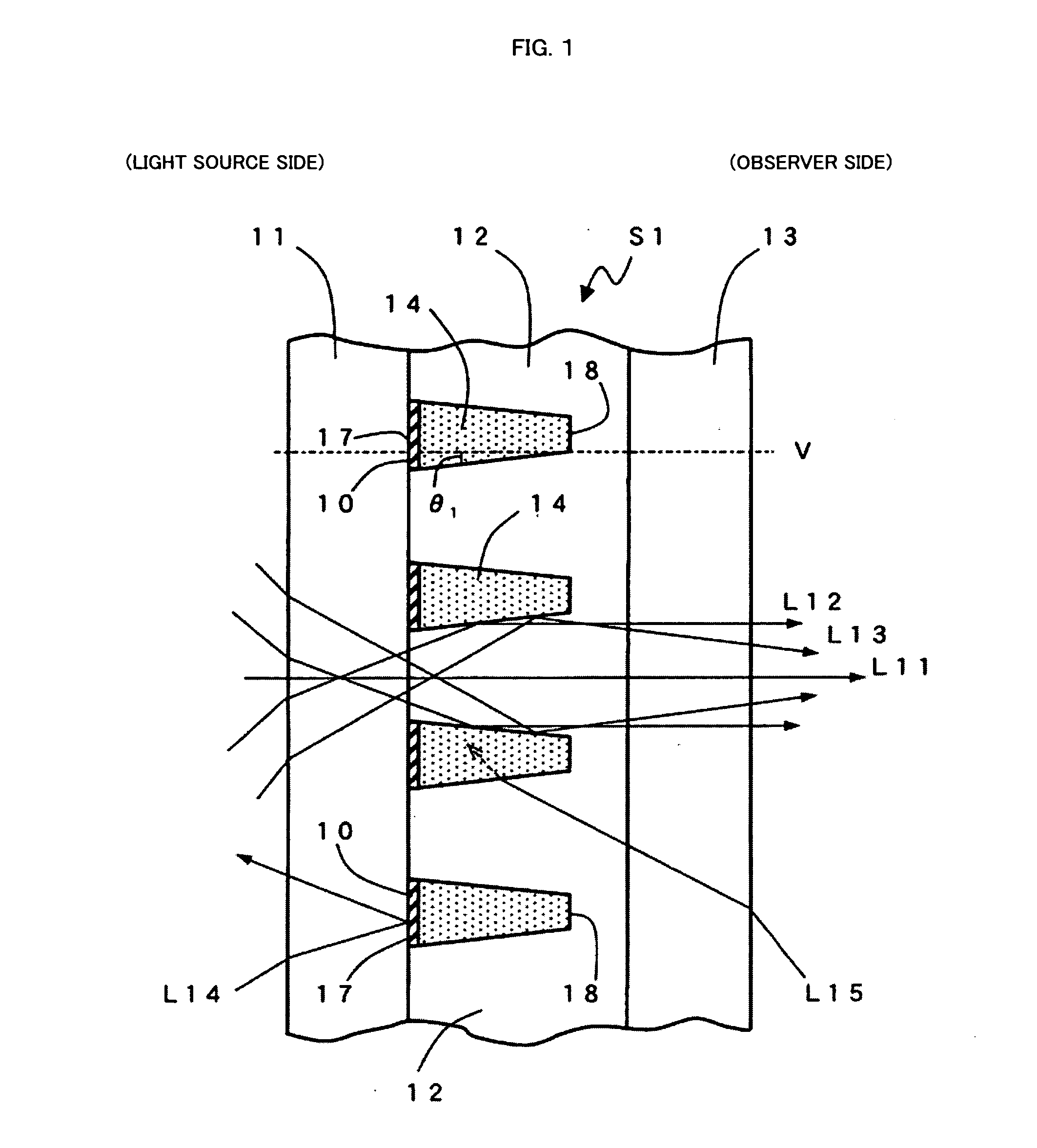
[0042]FIG. 1 is a diagram showing a cross section in one direction of a view angle controlling sheet S1 of a first embodiment of the present invention. In FIG. 1, the light source is disposed on the left side in the figure for outputting a diffusing light beam and the observer is situated on the right side of the figure. The view angle controlling sheet S1 comprises a light beam side base sheet 11, a lens part 12, and an observer side base sheet 13 attached from the light source side to the observer side successively. The lens part 12 is made of a substance having a refractive index of N1. Furthermore, the cross section wedge parts provided between the oblique sides of the lens parts 12, 12 adjacent in the vertical direction in the figure are substantially isosceles trapezoidal with the lower bottom surface 17 wider to the light source side and they are filled with a low refractive index substance having a refractive index of N2, which is lower than the refractive index N1 of the le...

second embodiment

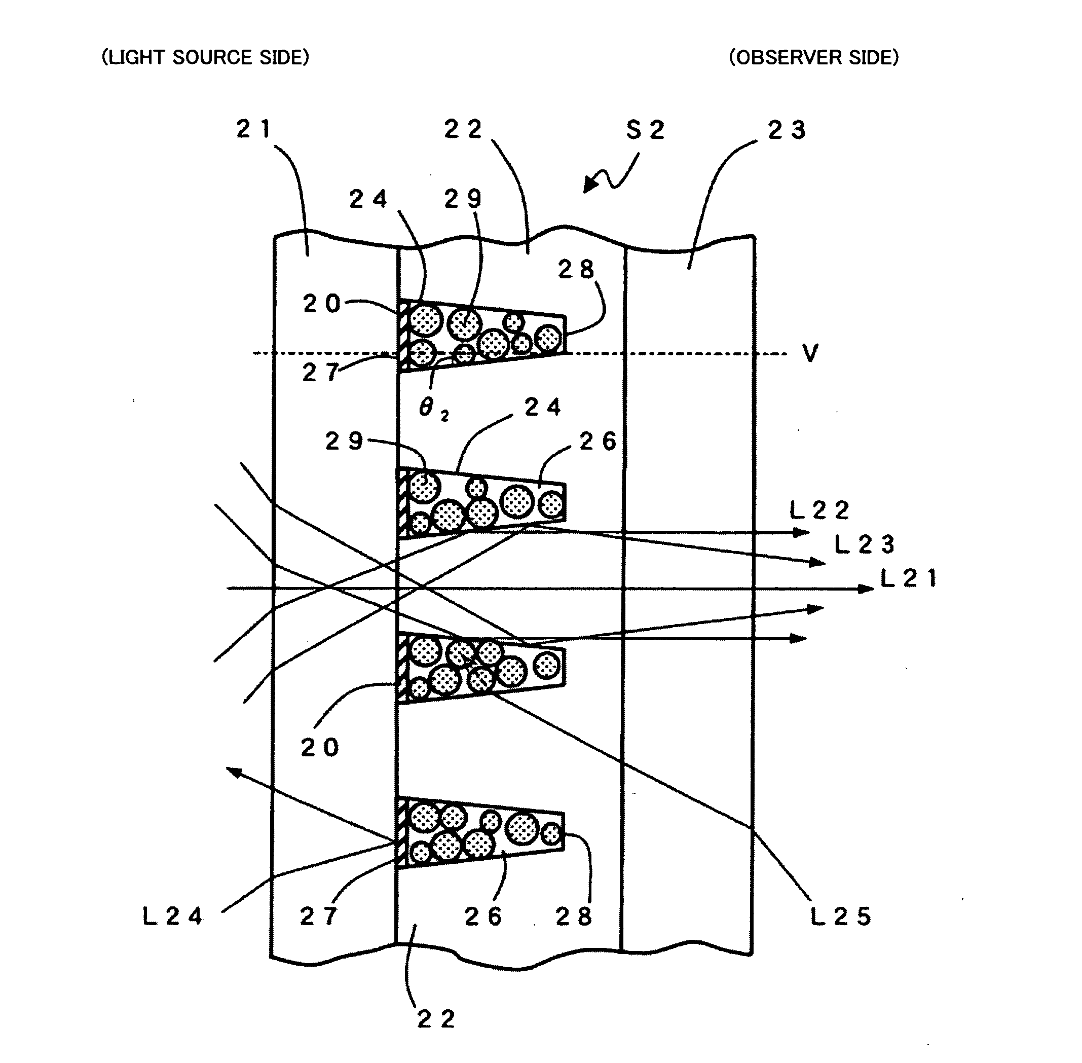
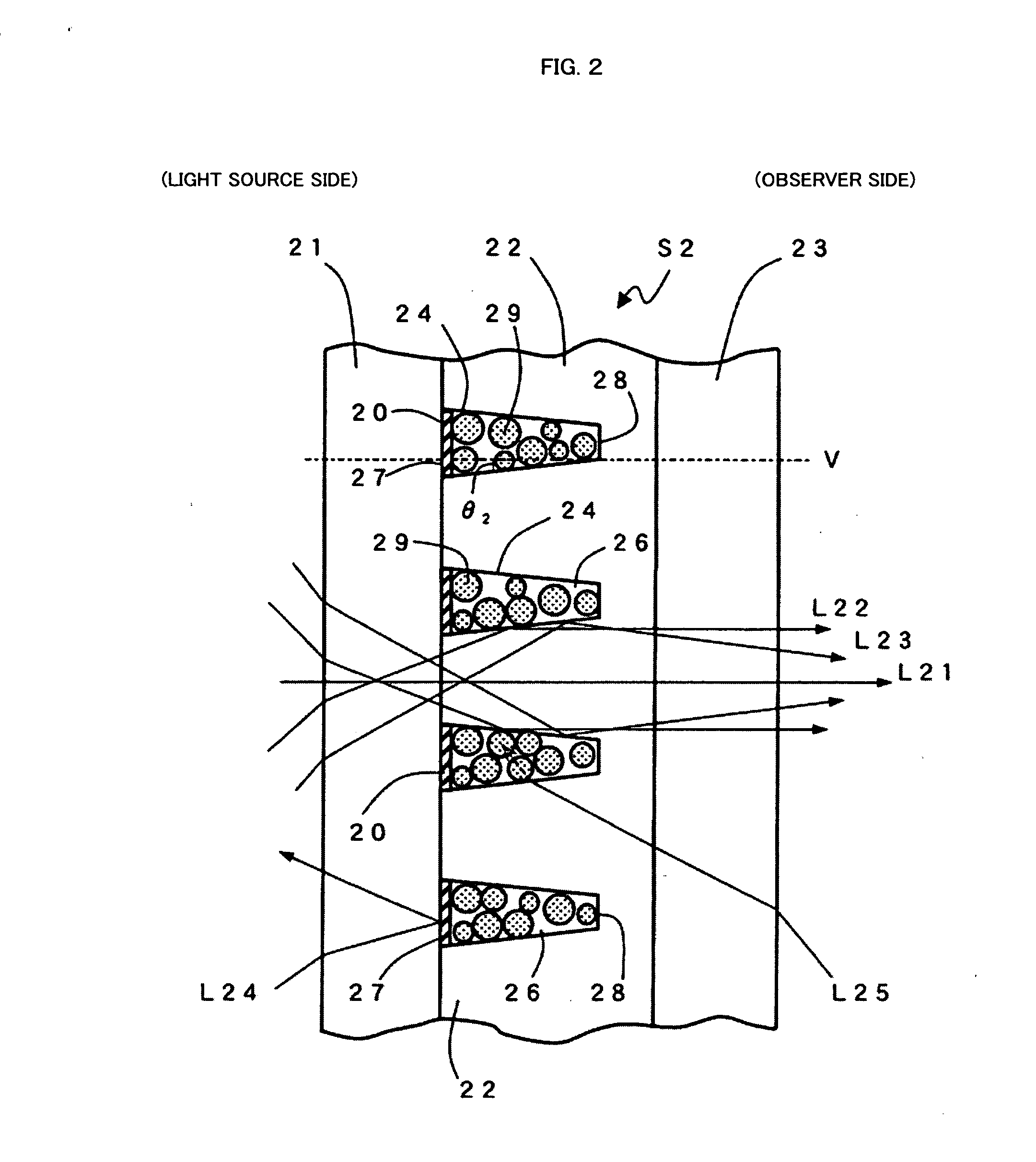
[0050]FIG. 2 shows a cross section of a view angle controlling sheet S2 of a second embodiment of the present invention. The view angle controlling sheet S2 comprises a light beam side base sheet 21, a lens part 22, and an observer side base sheet 23 attached from the light source side to the observer side successively. The lens part 22 is made of a substance having a high refractive index N1. Furthermore, the trapezoidal cross section wedge parts provided between the lens parts 22, 22 adjacent in the vertical direction in the figure are filled with a material with a light absorbing particle 29 added in a transparent substance as the main material having a refractive index of N2, which is lower than N1 (hereinafter it will be referred to as the “Transparent low refractive index substance 26”). The trapezoidal cross section wedge parts 24 have a lower bottom surface 27 to the observer side and an upper bottom surface 28 to the light source side. In the present invention, the base she...

third embodiment

[0067]FIG. 4 shows a cross section of a view angle controlling sheet S3 of a third embodiment of the present invention. In the view angle controlling sheet shown in FIG. 4, those having the same configuration as that of the constituent elements of the view angle controlling sheet shown in FIG. 2 have the same numerals as those used in FIG. 2 applied and the explanation thereof is optionally omitted. The view angle controlling sheet S3 comprises a light beam side base sheet 31, a lens part 32, and an observer side base sheet 33 attached from the light source side to the observer side successively. The lens part 32 is made of a substance having a high refractive index N1. Furthermore, the cross section trapezoidal portions unsymmetrical in the right and left direction 34, 34, . . . (hereinafter, it may be described as the “wedge parts 34, 34, . . . ”) provided between the cross section trapezoidal lens parts 32, 32 adjacent in the vertical direction in the figure are filled with a mat...


PUM


Abstract

A view angle controlling sheet to be disposed between the light source and the liquid crystal panel of a liquid crystal display apparatus, wherein the view angle controlling sheet has lens parts having a trapezoidal cross sectional shape arranged by a predetermined interval and the wedge parts between the adjacent lens parts is filled with a light absorbing material such that the wedge part has the top end disposed to the observer side and the bottom surface to the light source side and a light reflection layer provided to at least the bottom surface part on the light source side of the wedge part and with the premise that the angle formed by the slant face portion of the wedge part and the normal of the light output plane is θ, θ is in a range of 3°≦θ≦15°.

Description

BACKGROUND OF THE INVENTION [0001] 1. Field of the Invention [0002] The present invention relates to a view angle controlling sheet to be disposed between the light source and the liquid crystal panel of a liquid crystal display apparatus, having the function of preferably controlling the performance of the liquid crystal display apparatus, in particular, the light beam from the light source of the liquid crystal display, and a liquid crystal display apparatus using the same. [0003] 2. Description of the Related Art [0004] According to a liquid crystal display apparatus, in general, a wide view angle is preferred so that a preferable image can be obtained wherever the observer is. [0005] On the other hand, in the case of working in a commuter train or according to a liquid crystal display installed at a public place such as an ATM, it is inconvenient to have the screen peeped from the other people. In this case, a peep preventive function for ensuring the sight of only the observer ...

Claims


Application Information

Patent Timeline
IPC IPC(8): G01D11/28
CPCG02B5/003G02F1/1335G02F1/133524
Inventor AMEMIYA, HIROYUKIWATANABE, OSAMUICHIKAWA, NOBUHIKOGOTO, MASAHIRO
Owner DAI NIPPON PRINTING CO LTD
Why Eureka
Try Eureka