Developer supply container

a technology for developing equipment and supply containers, applied in the direction of instruments, electrographic process equipment, optics, etc., can solve the problems of scattering of developers and contamination of the outer surface of the developer supply container, and achieve the effect of suppressing contamination of the shutter of the developer receiving apparatus

Inactive Publication Date: 2006-05-18
CANON KK
View PDF9 Cites 42 Cited by
  • Summary
  • Abstract
  • Description
  • Claims
  • Application Information

AI Technical Summary

Benefits of technology

[0005] An object of the present invention is to provide a developer supply container capable of suppressing a contamination of a shutter of a developer receiving apparatus with developer.

Problems solved by technology

However, since the developer is very fine powder, there has been a possibility that during an operation for supplying an image forming apparatus with developer, the developer scatters.
Further, in the above descried constitution, the shutter of the developing apparatus is moved (opened or closed) together with the developer supply container from an initial stage of the rotation of the developer supply container, so that then is also a possibility that an outer surface of the developer supply container is contaminated due to the developer deposited on the shutter.

Method used


Image

  • Developer supply container
  • Developer supply container
  • Developer supply container

Examples


first embodiment

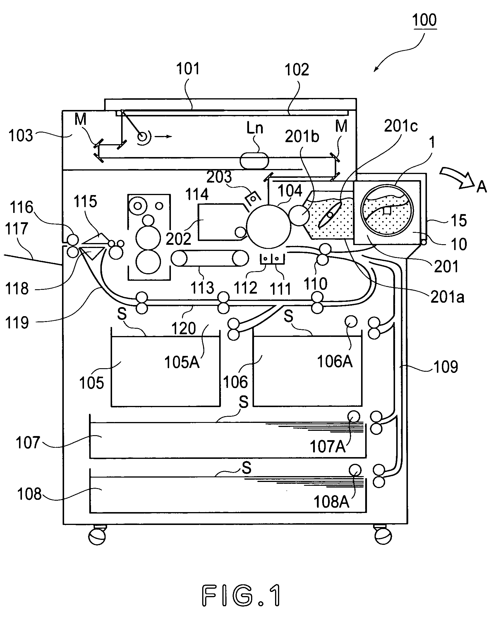
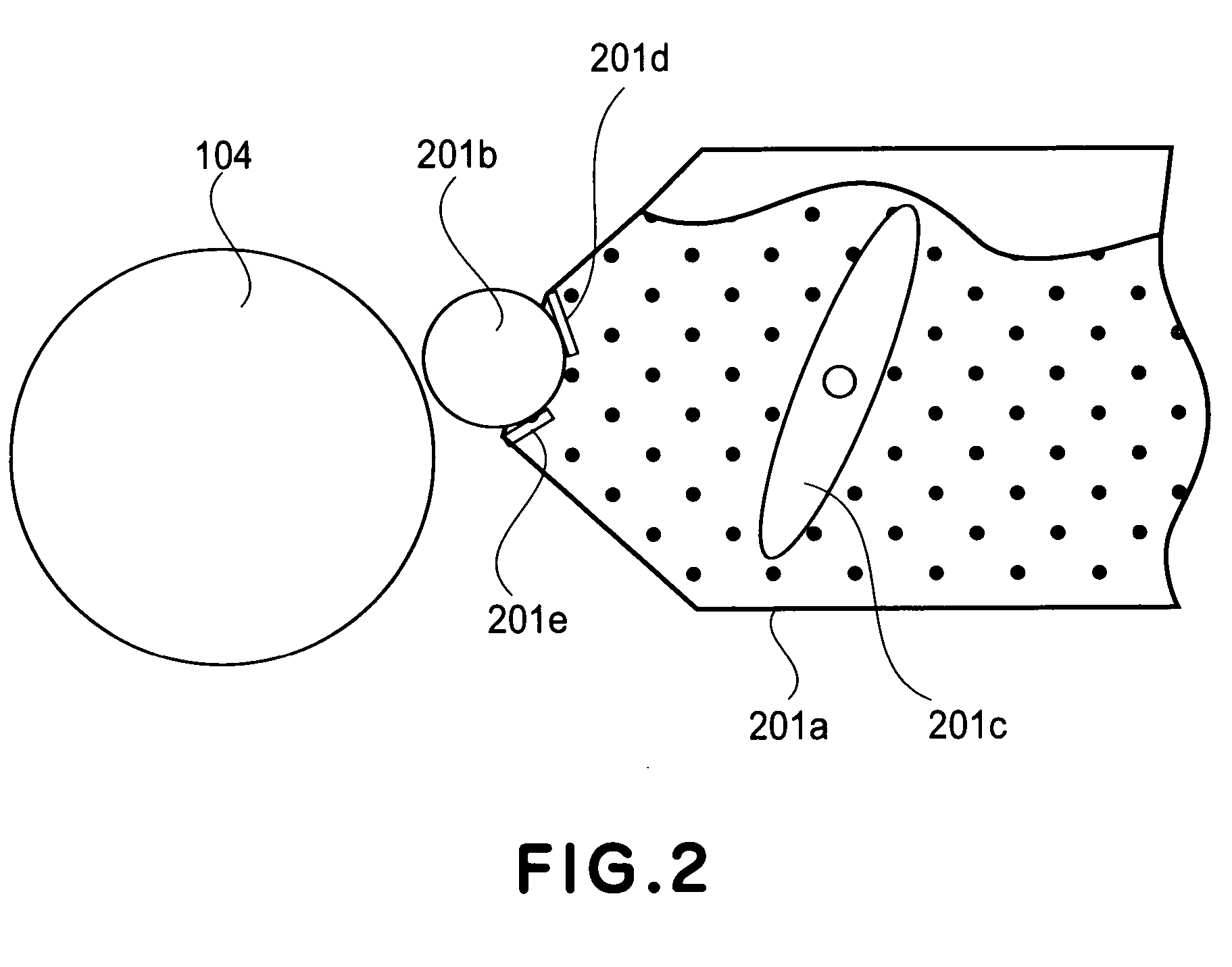
[0033] First, referring to FIG. 1, an electrophotographic copying machine, as an example of an electrophotographic image forming apparatus in which a developer supply container according to First Embodiment of the present invention is mounted, will be described with regard to its constitution.

[0034] In FIG. 1, designated by a referential number 100 is the main assembly of the electrophotographic copying machine (hereinafter referred to as an “apparatus main assembly”). Designated by a referential number 101 is an original, which is placed on an original-supporting glass plate 102. An optical image in accordance with the image formation (data) is formed on the electrophotographic photosensitive drum 104 by the combination of a plurality of mirrors M and a plurality of lenses Ln. Designated by referential numbers 105-108 are cassettes, from among which the cassette containing recording mediums (hereinafter referred to as “sheets”) S, which agree in size with the information inputted ...

second embodiment

[0072] Next, an image forming apparatus according to Second Embodiment will be described with reference to FIGS. 7(a) and 7(b). Incidentally, a basic constitution of the apparatus of this embodiment is the same as in First Embodiment described above, so that repetitive explanation thereof is omitted, and explanation is made with respect to a constitution characterizing this embodiment. Members or means having the same functions as those described in the above described embodiment are represented by the same referential numbers or symbols.

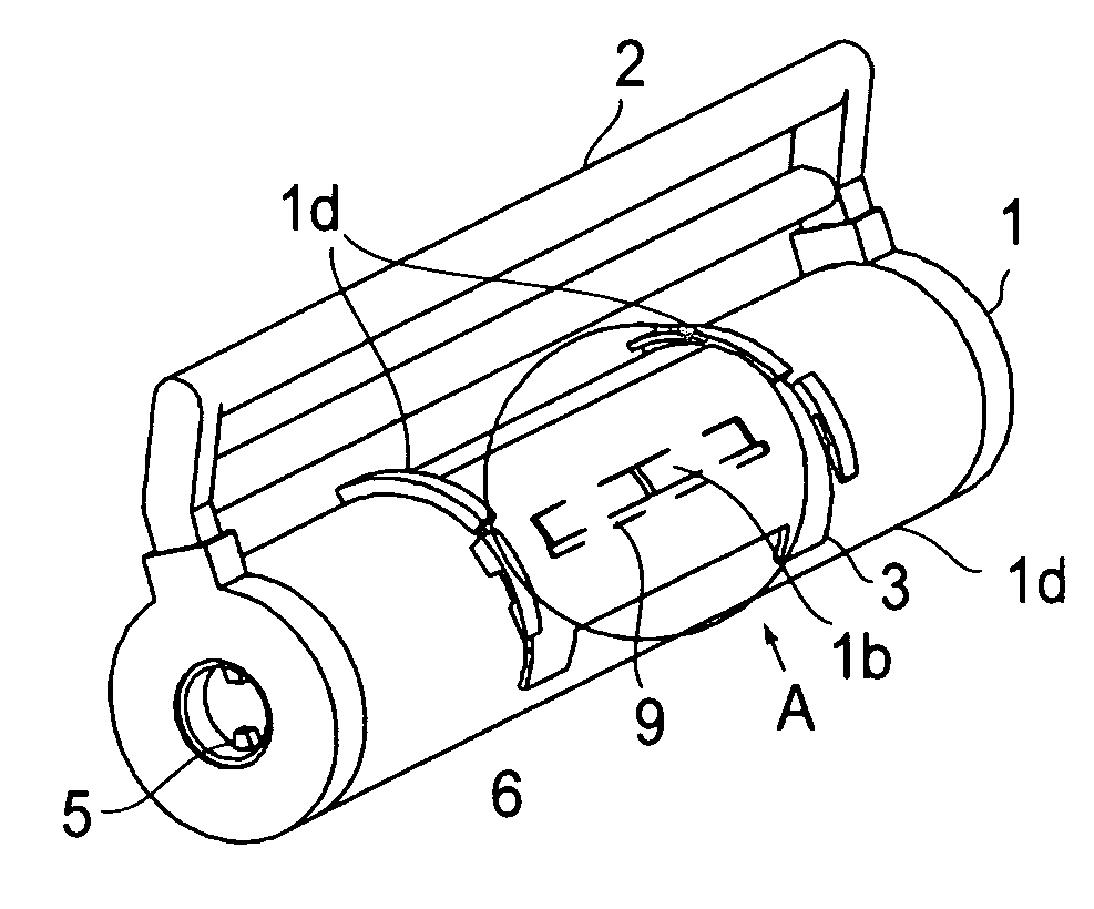
[0073] A developer supply container 1 in this embodiment is, as shown in FIG. 7(a), constituted so that it is mounted into a main assembly 100 of an image forming apparatus from a front side of the apparatus. More specifically, different from First Embodiment, a handle 2 is provided at an end, of a container body 1a in a lengthwise direction of the container body 1a, opposite to an end to which a drive gear member 5 is provided. Further, as shown i...

third embodiment

[0076] Next, an image forming apparatus according to Third Embodiment will be described with reference to FIGS. 8(a) and 8(b) and FIGS. 9(a) to 9(f). Incidentally, a basic constitution of the apparatus of this embodiment is the same as in First Embodiment described above, so that repetitive explanation thereof is omitted, and explanation is made with respect to a constitution characterizing this embodiment. Members or means having the same functions as those described in the above described embodiments are represented by the same referential numbers or symbols.

[0077] In First embodiment described above, such a constitution that the developer supply opening 1b is sealed with only the container shutter 3 is employed. In this embodiment, however, a constitution in which the developer supply opening 1b is sealed with a sealing film 14 and is further covered with the container shutter 3 as shown in FIG. 8(a) is employed in order to improve a sealing property of the developer supply open...


PUM


Abstract

A developer supply container is detachably mountable to a developer receiving apparatus having a receiving opening for receiving a developer and a shutter for opening and closing the receiving opening, the developer supply container includes an engaging portion which is engageable with the shutter and movable to open and close the shutter by movement of the developer supply container; and a cleaning member for cleaning the shutter when the developer supply container is moved relative to the shutter between a removal position permitting removal of the developer supply container from the developer receiving apparatus and a supply position at which the developer is supplied from the developer supply container to the developer receiving apparatus.

Description

FIELD OF THE INVENTION AND RELATED ART [0001] The present invention relates to a developer supply container for supplying a developer to a developer receiving apparatus for use in a copying machine, a facsimileing machine, a printer, etc. [0002] In the field of such an image forming apparatus as an electrophotographic copying machine, a printer, etc., a developer in the form of extremely minute particles has been used conventionally, and it has been a common practice that when the toner in the main assembly of an image forming apparatus is depleted by consumption, a toner supply container is used to supply the image forming apparatus with developer. However, since the developer is very fine powder, there has been a possibility that during an operation for supplying an image forming apparatus with developer, the developer scatters. For this reason, such a method that a developer supply container is disposed in a main assembly of an image forming apparatus and a developer is supplied ...

Claims


Application Information

Patent Timeline
Patent Type & Authority Applications(United States)
IPC IPC(8): G03G15/08
CPCG03G2215/067G03G15/0868G03G15/0872G03G15/08G03G15/06
Inventor MURAKAMI, KATSUYANAKAJIMA, NOBUO
Owner CANON KK
Why Eureka
Try Eureka