Connector

Active Publication Date: 2006-05-18
SUMITOMO WIRING SYST LTD
View PDF23 Cites 8 Cited by
  • Summary
  • Abstract
  • Description
  • Claims
  • Application Information

AI Technical Summary

Benefits of technology

[0010] The resistance alleviating portion achieves point contact when the lock contacts the edge of the engaging portion in the process of connecting the two housings. As a result, contact resistance is reduced and the lock arm hits the mating housing with a force that makes a loud hitting or clicking sound with an audible and ta

Problems solved by technology

Thus, the rear edge of the leading end of the above-described lock and the rear edge of the en

Method used


Image

  • Connector
  • Connector
  • Connector

Examples


Embodiment Construction

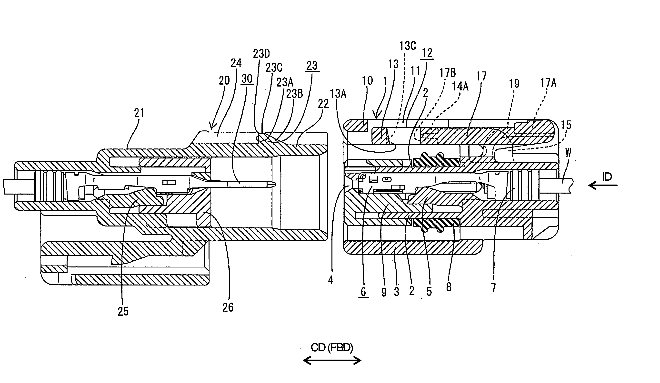
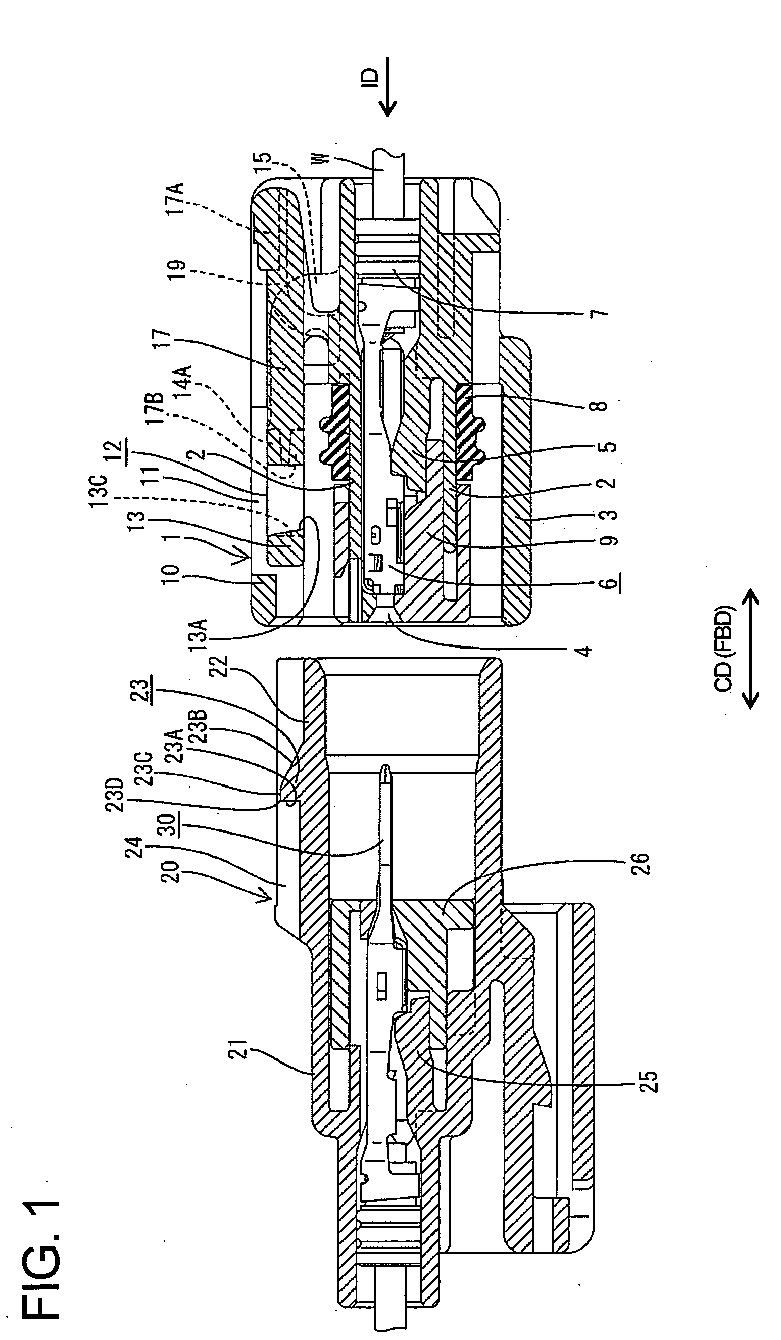
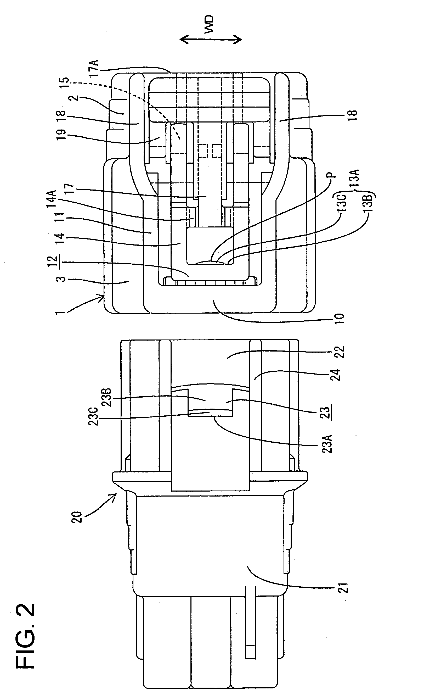
[0023] A connector assembly according to the invention is illustrated in FIGS. 1 to 6. The connector assembly has male and female connectors that are connectable with each other substantially along a connecting direction CD. In the following description, reference is made to FIG. 1 concerning the vertical direction. The vertical direction in FIG. 2 is referred to as the width direction WD, the transverse direction in FIG. 1 is referred to as forward and backward directions FBD, and ends to be connected are referred to as the front.

[0024] The male connector includes a male housing 20 made e.g. of a synthetic resin, and male terminals 30 are inserted into the male housing 20 from behind. The male housing 20 has a wide block-shaped main portion 21 and a receptacle 22 projects unitarily from the front surface of the main portion 21. The male housing 20 has locks 25 that lock the male terminals 30 in positions so that tabs of the male terminals 30 project from the back surface of the re...


PUM


Abstract

A lock arm (12) on a female housing (1) is deformed at an intermediate stage of connecting the female housing (1) with a mating male housing (20). A lock (13) at the leading end of the lock arm (12) contacts an edge (23D) of an engaging portion (23) on the male housing (20) and then parts therefrom by canceling a rubbing state. The lock arm (12) then restores resiliently and the lock (13) engages the engaging portion (23) to lock the housings (1, 20) in a properly connected state. At least one of the lock (13) and the edge (23D) of the engaging portion (23) that rub against each other immediately before the proper connection of the two housings (1, 20) has a resistance alleviating portion (13C) with an apex locally projecting toward the other rubbed part.

Description

BACKGROUND OF THE INVENTION [0001] 2. Field of the Invention [0002] The invention relates to a connector. [0003] 2. Description of the Related Art [0004] U.S. Pat. No. 5,336,101 discloses a connector assembly with male and female housings that can be connected together. A lock arm is provided on an upper surface of the female housing and a lock is formed on the leading end of the lock arm. The lock arm can pivot about the base end so that the lock at the leading end of the lock arm displaces. An engaging projection is provided on the upper surface of the male housing. The lock moves onto the engaging projection during the connection of the male and female housings. The lock then contacts the rear edge of engaging projection and parts from the rear edge that have been rubbed against. The lock arm then returns resiliently while following a pivoting path. In this way, the lock engages the engaging projection to lock the male and female housings in their connected state. [0005] The rear...

Claims


Application Information

Patent Timeline
IPC IPC(8): H01R13/627
CPCH01R13/6272
Inventor TOYODA, YUKIHIRO
Owner SUMITOMO WIRING SYST LTD
Why Eureka
Try Eureka