Simple crest factor reduction technique for non-constant envelope signals

a crest factor and non-constant envelope technology, applied in the direction of transmission, electrical equipment, etc., can solve the problems of high power consumption, high power consumption, cost and size of the system, and achieve the effect of improving the power handling of the rf amplifier, boosting the power handling of the amplifier, and low-cost crest factor

Inactive Publication Date: 2006-05-18
ANVARI KIOMARS
View PDF2 Cites 15 Cited by
  • Summary
  • Abstract
  • Description
  • Claims
  • Application Information

AI Technical Summary

Benefits of technology

[0002] According to the invention, a low-cost Crest Factor reduction circuit, for use with RF amplifier, uses a plurality of simple and accurate circuits in conjunction with intelligent signal processing to improve power handling of the RF amplifier. By intelligent, it is meant that the Crest Factor reduction module has features of removing the unwanted signals after applying the crest factor reduction function. The Crest Factor reduction module uses the amplifier input which could be a baseband, an IF or RF signal as its input and conditions the input before applying to the amplifier. The conditioning or Crest Factor reduction helps to boost the power handling of the amplifier or acts more linearly. The inputs to the Crest Factor reduction should be within a limit that can be handled by the Crest Factor reduction module.

Problems solved by technology

This component has a major contribution in cost, power consumption, and size of the system.
The higher the linearity, the higher the power consumption, cost and size.

Method used


Image

  • Simple crest factor reduction technique for non-constant envelope signals
  • Simple crest factor reduction technique for non-constant envelope signals
  • Simple crest factor reduction technique for non-constant envelope signals

Examples


Embodiment Construction

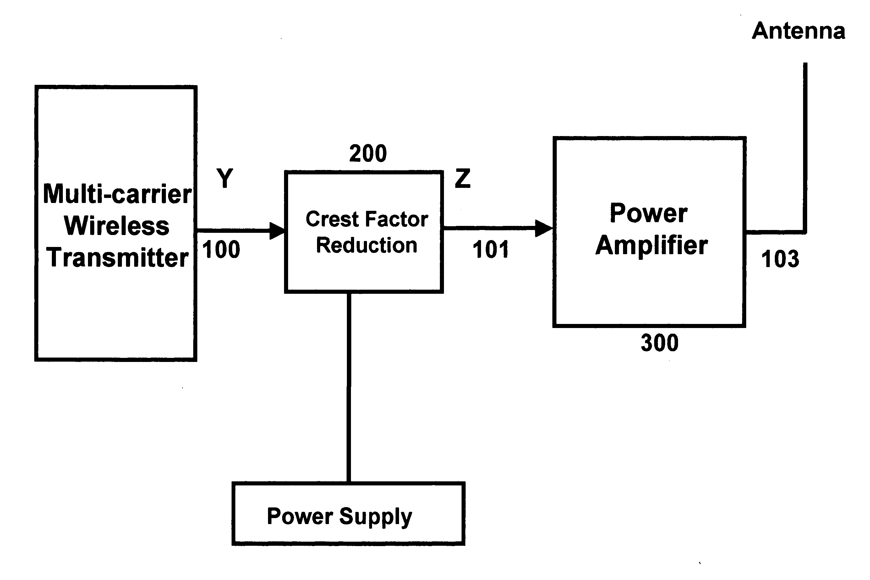
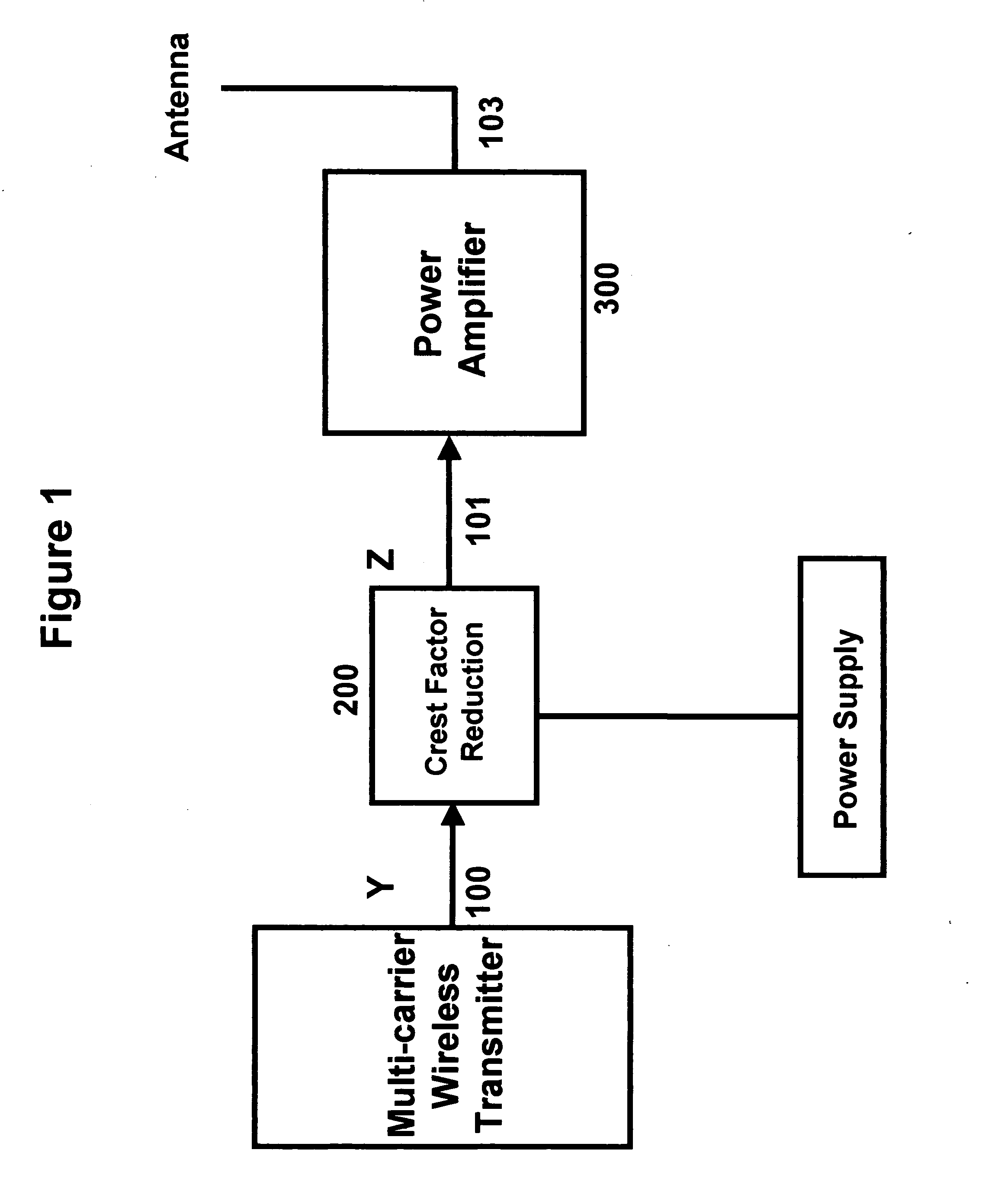
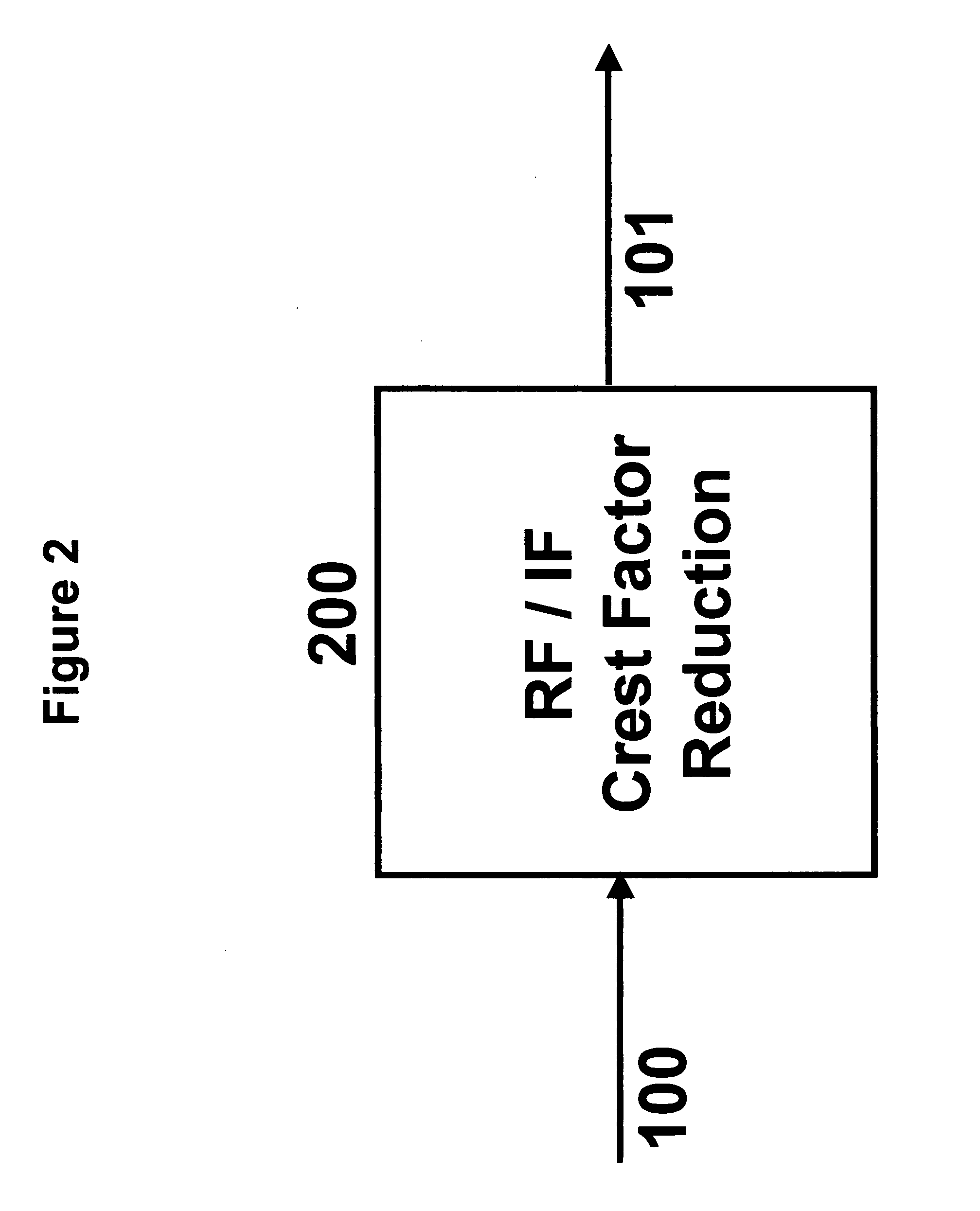
[0015] In a first preferred embodiment the Crest Factor reduction circuit monitors the signal strength of the input signal channels using the input receiver and finds the frequency and channel number of the input signals. In a second preferred embodiment of the invention, the Crest Factor reduction circuit is implemented at RF / IF frequency. In a third preferred embodiment of the invention, the Crest Factor reduction circuit uses sub-harmonic sampling to convert RF or IF signals to digital baseband signal. In a fifth preferred embodiment the input signal is conditioned or Crest Factor reduced using the baseband signal. In a sixth embodiment the Crest Factor reduction is applied on baseband real signal. In a seventh embodiment the Crest Factor reduction is applied on both real and imaginary components of the baseband signal. In an eighth embodiment the signal is amplitude clipped or limited either in analog or digital domain. In a ninth embodiment the baseband clipping circuit uses th...


PUM


Abstract

A technique for Crest Factor reduction of non-constant envelope signals is described. The input to any nonlinear circuit is modified by a Crest Factor reduction circuit, prior to being applied to the nonlinear circuit. The Crest Factor reduction circuit can either be performed at baseband or RF / IF frequencies. When performed at baseband the real and imaginary components of the baseband signal individually are applied to the Crest Factor reduction circuit. When performed at RF / IF the real signal is directly applied to the Crest Factor reduction circuit. The Crest Factor reduction divides the signal in two equal components one in-phase and one quadrature phase. Each component is then individually clipped based on magnitude of the real or complex signal and then filtered before being combined again by a combiner that 90 degree phase shifts the in-phase component before combining . In the case of RF / IF the clipped signal is bandpass filtered. The Crest Factor reduction could be performed in digital or analog domain.

Description

BACKGROUND OF INVENTION [0001] The present invention relates to a Crest Factor reduction circuit to boost the out put power of a wireless RF amplifier. The Crest Factor reduction circuit input could be baseband, intermediate frequency (IF), or RF signal. and its output is the Crest Factor reduced baseband or IF / RF signal as a new input to the amplifier. In any wireless communication system one of the critical components is the power amplifier. This component has a major contribution in cost, power consumption, and size of the system. The main reason is the requirement of wireless radio communication system for linear amplifiers. The higher the linearity, the higher the power consumption, cost and size. In order to minimize the cost, size and power consumption there is a need for techniques that overcome this problem. This invention conquers these challenges by using a simple and accurate Crest Factor reduction module used at the input to the amplifier. SUMMARY OF INVENTION [0002] Ac...

Claims


Application Information

Patent Timeline
Patent Type & Authority Applications(United States)
IPC IPC(8): H04B1/04
CPCH04B1/0475
Inventor ANVARI, KIOMARS
Owner ANVARI KIOMARS
Why Eureka
Try Eureka