System and method for displaying and using non-numeric graphic elements to control and monitor a vision system

a visual system and graphic element technology, applied in the field of visual systems, can solve the problems of difficult to arrange the photodetectors, the simple sensing of light intensity reflected from a point on the object is often insufficient for inspection, and the automatic inspection using photodetectors

Active Publication Date: 2006-05-18
COGNEX TECH & INVESTMENT
View PDF48 Cites 47 Cited by
  • Summary
  • Abstract
  • Description
  • Claims
  • Application Information

AI Technical Summary

Problems solved by technology

Automatic inspection using photodetectors has various disadvantages, however, including:
Simple sensing of light intensity reflected from a point on the object is often insufficient for inspection.
It may be hard to arrange the photodetectors when many points on an object need to be inspected.
Interference may be due to space limitations, crosstalk from the light sources, or other factors.
The cost of performing a line changeover, and the risk of human error involved, often offset the low cost and simplicity of the photodetectors.
This requirement may add additional cost and complexity that can offset the low cost and simplicity of the photodetectors.
Machine vision systems have disadvantages compared to an arrangement of photodetectors, including:
They are relatively expensive, often costing ten times more than an arrangement of photodetectors.
They can be difficult to set up, often requiring people with specialized engineering training.
Furthermore, the decision time tends to vary significantly and unpredictably from object to object.
Machine vision systems have limitations that arise because they make decisions based on a single image of each object, located in a single position in the field of view (each object may be located in a different and unpredictable position, but for each object there is only one such position on which a decision is based).
The use of only a single perspective often leads to incorrect decisions.
It has long been observed, for example, that a change in perspective of as little as a single pixel can in some cases change an incorrect decision to a correct one.
Also, the limitations of machine vision systems arise in part because they operate too slowly to capture and analyze multiple perspectives of objects in motion, and too slowly to react to events happening in the field of view.

Method used


Image

  • System and method for displaying and using non-numeric graphic elements to control and monitor a vision system
  • System and method for displaying and using non-numeric graphic elements to control and monitor a vision system
  • System and method for displaying and using non-numeric graphic elements to control and monitor a vision system

Examples


Embodiment Construction

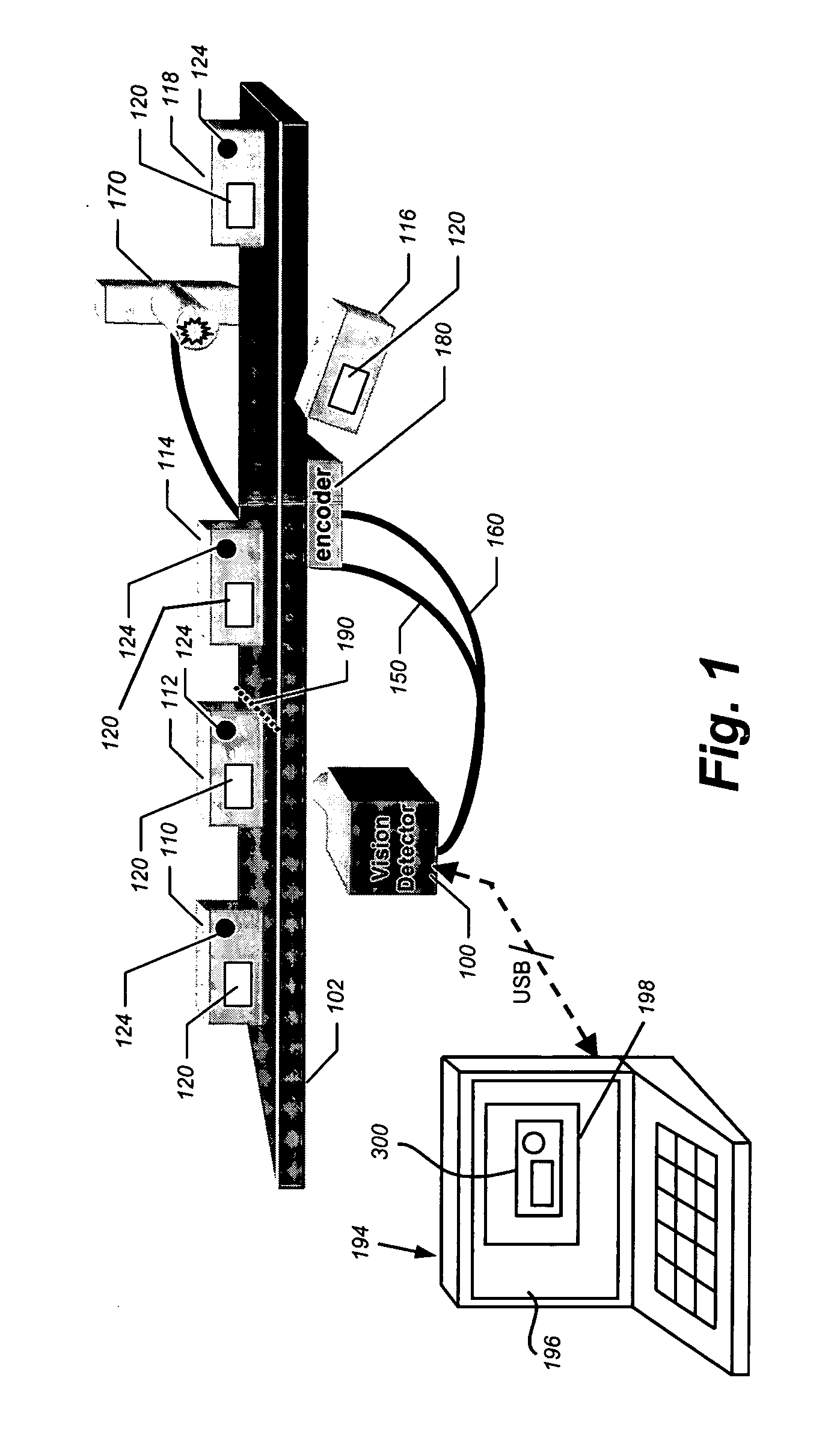
[0063]FIG. 5 shows a high-level block diagram for a vision detector 500, which can be used in connection with an embodiment of this invention. The vision detector 500 operates in a production environment. It is expressly contemplated that the teachings of this invention are applicable to any type of vision system that captures and analyzes images of objects and provides a means for monitoring the function of certain operating parameters of the vision system via an HMI. The HMI may be either permanently connected or removable, and where removable, typically is used for setup of operating parameters and monitoring / testing of vision system function based upon the set operating parameters. Thus the vision detector used herein is exemplary of a variety of vision systems that employ settable operating parameters through an HMI.

[0064] The vision detector 500 of this exemplary embodiment functions generally in accordance with principles described in the above-incorporated-by-reference METH...


PUM


Abstract

This invention provides a system and method for employing GUI-based non-numeric slide buttons and bar meters to setup and monitor operating parameters of a vision system (the term “vision system” as used herein including the above-described vision detector). Such parameters can include, but are not limited to the threshold at which a feature is activated in viewing an image. Operating parameters also include the under-lying range of contrast values and levels of brightness intensities (or by input inversion, the level of darkness) recognized and acted upon by the vision system. Graphical representations of operating parameters are displayed in a parameter box on the GUI with moving bars that are shaded, patterned or colored so as to provide a relative level between two extremes on a scale of the given operating parameter. The endpoints of the scale can be established by analyzing the relevant extremes on a subject image view. The current level of the given parameter is displayed as a bar that extends a distance along the scale that is proportional to the current level of the parameter along the scale. Input of operating parameter settings with respect to the scale is made by moving a setting slider along the scale between the extremes. The position of the slider establishes the user-input setting relative to the scale. In an illustrative embodiment, scales, level bars and setting sliders can also be displayed on the image view itself, adjacent to a given image view feature, which is the subject of the scale.

Description

RELATED APPLICATION [0001] This application is related to co-pending and commonly assigned U.S. patent application Ser. No. 10 / 865,155, entitled METHOD AND APPARATUS FOR VISUAL DETECTION AND INSPECTION OF OBJECTS, by William M. Silver, filed Jun. 9, 2004, the teachings of which are expressly incorporated herein by reference.FIELD OF THE INVENTION [0002] This invention relates to vision systems, and more particularly to Graphical User Interface (GUI) elements for monitoring and controlling such vision systems. BACKGROUND OF THE INVENTION [0003] Industrial manufacturing relies on automatic inspection of objects being manufactured. One form of automatic inspection that has been in common use for decades is based on optoelectronic technologies that use electromagnetic energy, usually infrared or visible light, photoelectric sensors, and some form of electronic decision making. [0004] One well-known form of optoelectronic automatic inspection uses an arrangement of photodetectors. A typi...

Claims


Application Information

Patent Timeline
Patent Type & Authority Applications(United States)
IPC IPC(8): G06F3/00
CPCG01N21/90G05B2219/32128G06F3/04847
Inventor MIRTICH, BRIAN V.EAMES, ANDREWPHILIPS, BRIAN S.TREMPLAY, ROGER J. IIKEAUNG, JOHN F.WHITMAN, STEVEN
Owner COGNEX TECH & INVESTMENT
Why Eureka
Try Eureka