Cooling device

a cooling device and cooling technology, applied in the field of cooling systems, can solve the problems of increasing the cost of components and installation of the cooling system, the noise of the compressor operation, and so as to avoid the cooling and defrosting efficiency decrease, the effect of avoiding the cooling efficiency of the evaporator and low cos

Inactive Publication Date: 2006-05-25
HOSHIZAKI ELECTRIC CO LTD
View PDF2 Cites 45 Cited by
  • Summary
  • Abstract
  • Description
  • Claims
  • Application Information

AI Technical Summary

Benefits of technology

[0006] It is, therefore, an object of the present invention to provide a cooling system at a low cost, wherein the compressor is installed at an appropriate place apart from the evaporator in such a manner capable of avoiding a decrease of the cooling and defrosting efficiency caused by shortage of refrigerant and of avoiding a decrease of the cooling efficiency of the evaporator caused by exhaust heat of the compressor.
[0007] According to the present invention, the object is accomplished by providing a cooling system having a compressor for supplying refrigerant under pressure, a condenser for cooling and condensing the refrigerant supplied from the compressor, a liquid receiver arranged to temporarily store the condensed refrigerant supplied from the condenser, an expansion valve for expanding the refrigerant supplied from the liquid receiver, and an evaporator arranged to effect evaporation of the expanded refrigerant for cooling the surrounding thereof, wherein the cooling system comprises a bypass conduit arranged to bypass the liquid receiver and expansion valve and flow passage changeover means electrically controlled to selectively connect a supply passage of the refrigerant to the liquid receiver and expansion valve and to the bypass conduit so that the supply passage of refrigerant is connected to the liquid receiver and expansion valve during operation at a cooling mode and is connected to the bypass conduit during operation at a defrost mode.
[0008] In the cooling system constructed as described above, the compressor can be installed at an appropriate place apart from the evaporator without the provision of any elongated conduit for defrost. Accordingly, the cooling system can be provided in such a manner to avoid decrease of the cooling and defrosting efficiency caused by shortage of refrigerant, problems caused by noises of the compressor and decrease of the cooling efficiency of the evaporator caused by exhaust heat of the compressor.
[0009] Accordingly to an aspect of the present invention, there is provided a cooling system having a compressor for supplying refrigerant under pressure, a condenser for cooling and condensing the refrigerant supplied from the compressor, a liquid receiver arranged to temporarily store the condensed refrigerant supplied from the condenser, an expansion valve for expanding the refrigerant supplied from the liquid receiver, and an evaporator arranged to effect evaporation of the expanded refrigerant for cooling the surrounding thereof, wherein the cooling system comprises a bypass conduit arranged to bypass the expansion valve and flow passage changeover means electrically controlled to selectively connect the supply passage of refrigerant to the expansion valve and to the bypass conduit so that the supply passage of refrigerant is connected to the expansion valve during operation at a cooling mode and is connected to the bypass conduit during operation at a defrost mode.
[0010] In the cooling system described above, it is able to avoid decrease of the cooling and defrosting efficiency caused by shortage of refrigerant, problems caused by noises of the compressor and decrease of the cooling efficiency of the evaporator caused by exhaust heat of the compressor. As the refrigerant from the liquid receiver is supplied to the evaporator through the bypass conduit during operation at the defrost mode, the refrigerant stored in the liquid receiver can be utilized without uselessness to enhance the defrost efficiency.

Problems solved by technology

In the case that the compressor was installed at a place near the evaporator in the cooling system, noises in operation of the compressor and decrease of the cooling efficiency of the evaporator caused by exhaust heat of the compressor were problems for solution.
If the compressor was installed at a place apart from the evaporator to solve the problems in the cooling system, the defrost conduit for direct supply of the refrigerant from the compressor to the evaporator would be elongated, resulting in an increase of cost of the component parts and cost for installation of the cooling system.

Method used


Image

  • Cooling device
  • Cooling device
  • Cooling device

Examples


first embodiment

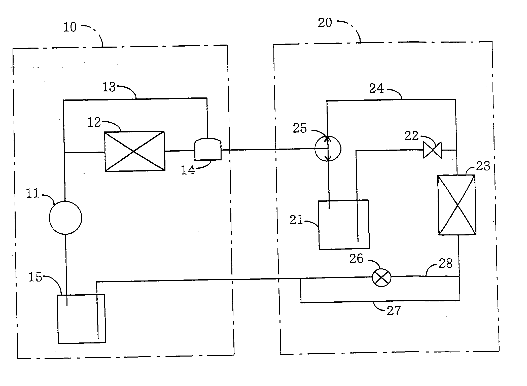
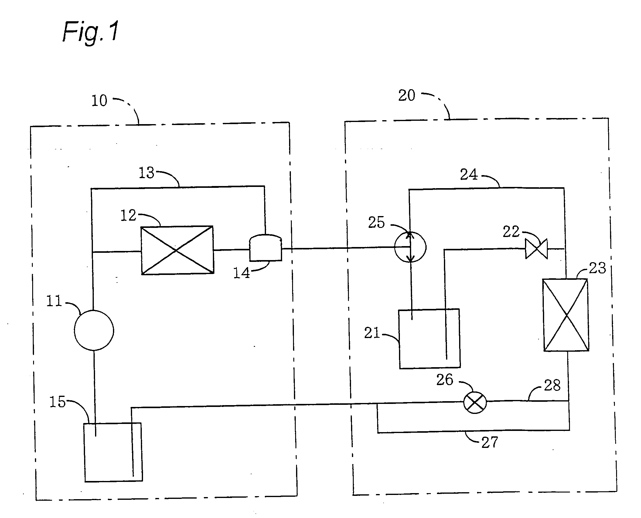
[0017] Hereinafter, a first embodiment of the present invention will be described with reference to the drawings. In this embodiment, a cooling system according to the present invention is adapted to an ice making machine. As shown in FIG. 1, the cooling system comprises an outdoor unit 10 and an indoor unit 20. The outdoor unit 10 is composed of a compressor 11 for supplying refrigerant under pressure, a condenser 12 for condensing the refrigerant supplied from the compressor 11. The indoor unit 20 is composed of a liquid receiver 21 installed to temporarily store the condensed refrigerant supplied from the condenser 12, an expansion valve 22 placed to expand the condensed refrigerant supplied from the liquid receiver 21 and an evaporator 23 arranged to evaporate the expanded refrigerant from the expansion valve 22.

[0018] The outdoor unit 10 further comprises a bypass conduit 13 arranged to bypass the condenser 12 and a pressure adjustment valve 14 provided to maintain the pressur...

second embodiment

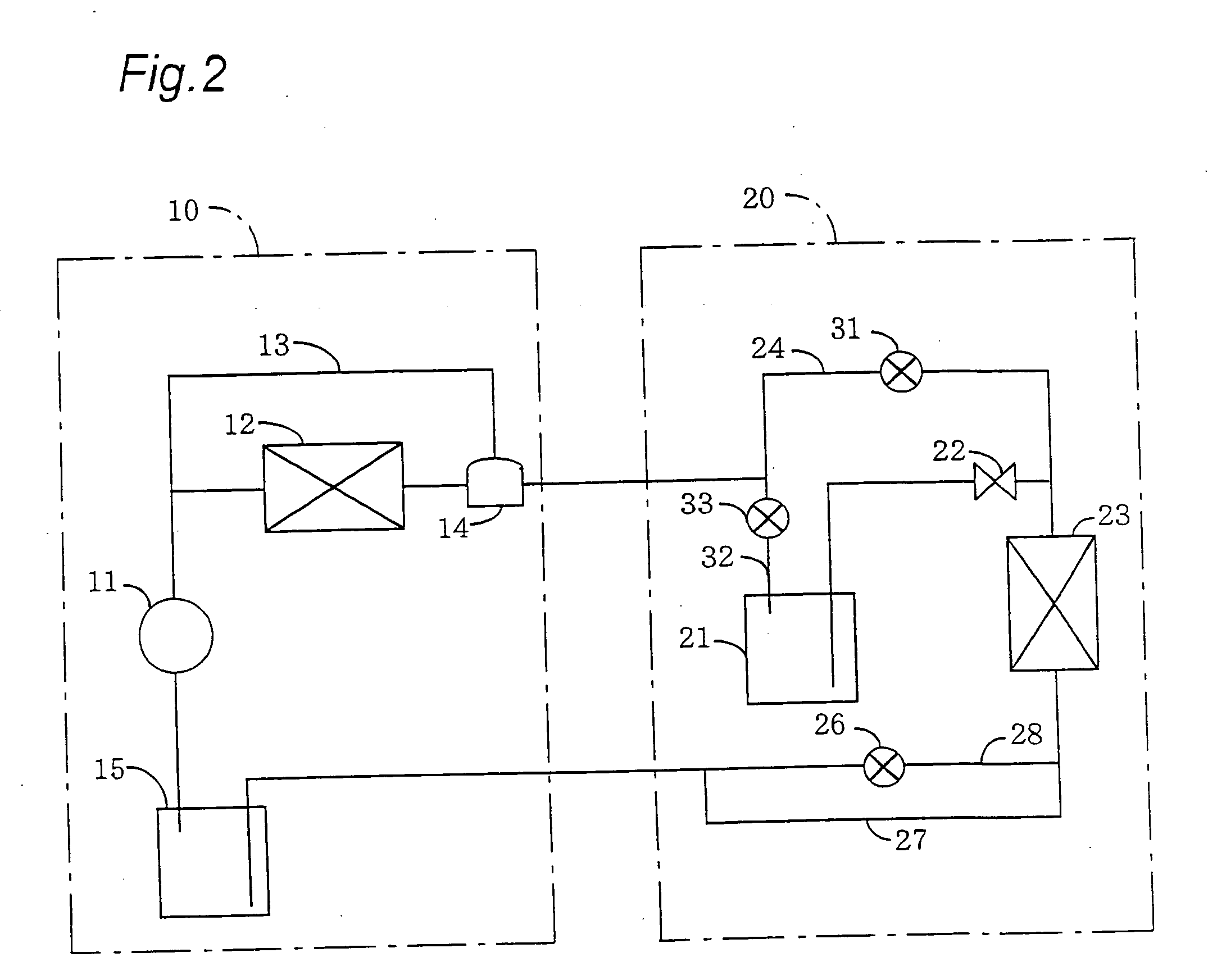
[0026] Hereinafter, a second embodiment of the present invention will be described with reference to the drawings. In this second embodiment, as shown in FIG. 2, the three-way valve 25 in the first embodiment is replaced with an on-off valve 31, and an on-off valve 33 is disposed in a conduit 32 for supply of the refrigerant into the liquid receiver 21.

[0027] The on-off valve 31 is disposed in the bypass conduit 24 to be electrically controlled in operation of the system. In operation at the cooling mode, the on-off valve 31 is maintained in a closed condition to interrupt the flow of refrigerant passing through the bypass conduit 24. In operation at the defrost mode, the on-off valve 31 is opened to permit the flow of refrigerant passing through the bypass conduit 24. Thus, when the on-off valve 31 is closed during operation at the cooling mode, the refrigerant under pressure from compressor 11 is supplied to the side of liquid receiver 21 and expansion valve 22. When the on-off v...

third embodiment

[0029] Hereinafter, a third embodiment of the present invention will be described with reference to the drawings. In this third embodiment, as shown in FIG. 3, the on-off valve 33 in the second embodiment is replaced with a check valve 41 disposed in the conduit 32 for connection to the liquid receiver 21. The check valve 41 permits the flow of refrigerant from the condenser 12 and interrupts the flow of refrigerant from the liquid receiver 21. Thus, the check valve 41 is useful to avoid a reverse flow of refrigerant remained in the liquid receiver 21 during operation at the defrost mode.


PUM


Abstract

In a cooling system having a compressor for supplying refrigerant under pressure, a condenser for condensing the refrigerant supplied from the compressor, a liquid receiver arranged to temporarily store the condensed refrigerant supplied from the condenser, an expansion valve for expanding the refrigerant supplied from the liquid receiver, and an evaporator arranged to effect evaporation of the expanded refrigerant for cooling the surrounding thereof, a bypass conduit is arranged to bypass the liquid receiver and expansion valve, and an electrically operated flow passage changeover valve is provided to selectively connect a supply passage of refrigerant to the liquid receiver and expansion valve and to the bypass conduit so that the supply passage of refrigerant is connected to the liquid receiver and expansion valve during operation at a cooling mode and is connected to the bypass conduit during operation at a defrost mode.

Description

BACKGROUND OF THE INVENTION [0001] 1. Field of the Invention [0002] The present invention relates to a cooling system adapted to an ice making machine, a refrigerator, a freezer, an air conditioner and the like, more particularly to a cooling system which is operated alternately at a cooling mode and a defrost mode. [0003] 2. Discussion of the Prior Art [0004] A conventional cooling system of this kind comprises a compressor for supplying refrigerant under pressure, a condenser for cooling and condensing the refrigerant supplied from the compressor, a liquid receiver arranged to temporarily store the condensed refrigerant supplied from the condenser, an expansion valve for expanding the refrigerant supplied from the liquid receiver, and an evaporator arranged to effect evaporation of the expanded refrigerant for cooling the surrounding thereof. In the cooling system, a supply conduit of the refrigerant from the compressor to the condenser and a supply conduit of the refrigerant from...

Claims


Application Information

Patent Timeline
Patent Type & Authority Applications(United States)
IPC IPC(8): F25D21/06F25B41/00F25B49/00
CPCF25B41/043F25B47/022F25B2400/0403F25B2400/0411F25B2400/0415F25B2400/16F25B41/22
Inventor YOSHIDA, KAZUHIROSEKI, KAZUYOSHIHIRANO, AKIHIKOYATORI, MASAHIDETOYA, CHIYOSHI
Owner HOSHIZAKI ELECTRIC CO LTD
Why Eureka
Try Eureka