Modularized cooler

Inactive Publication Date: 2006-05-25
FORWARD ELECTRONICS CO LTD
View PDF13 Cites 16 Cited by
  • Summary
  • Abstract
  • Description
  • Claims
  • Application Information

AI Technical Summary

Benefits of technology

[0008] By means of the arrangement of the at least two heat radiator modules and the connection of the at least one connecting tube between the at least two heat radiator modules, the invention eliminates the formation of wind resistance as seen in the prior art design due to staggered arrangement of heat-exchange tubes, and greatly reduces the dimens

Problems solved by technology

The staggered arrangement of the heat-exchange tube

Method used


Image

  • Modularized cooler
  • Modularized cooler
  • Modularized cooler

Examples


Example

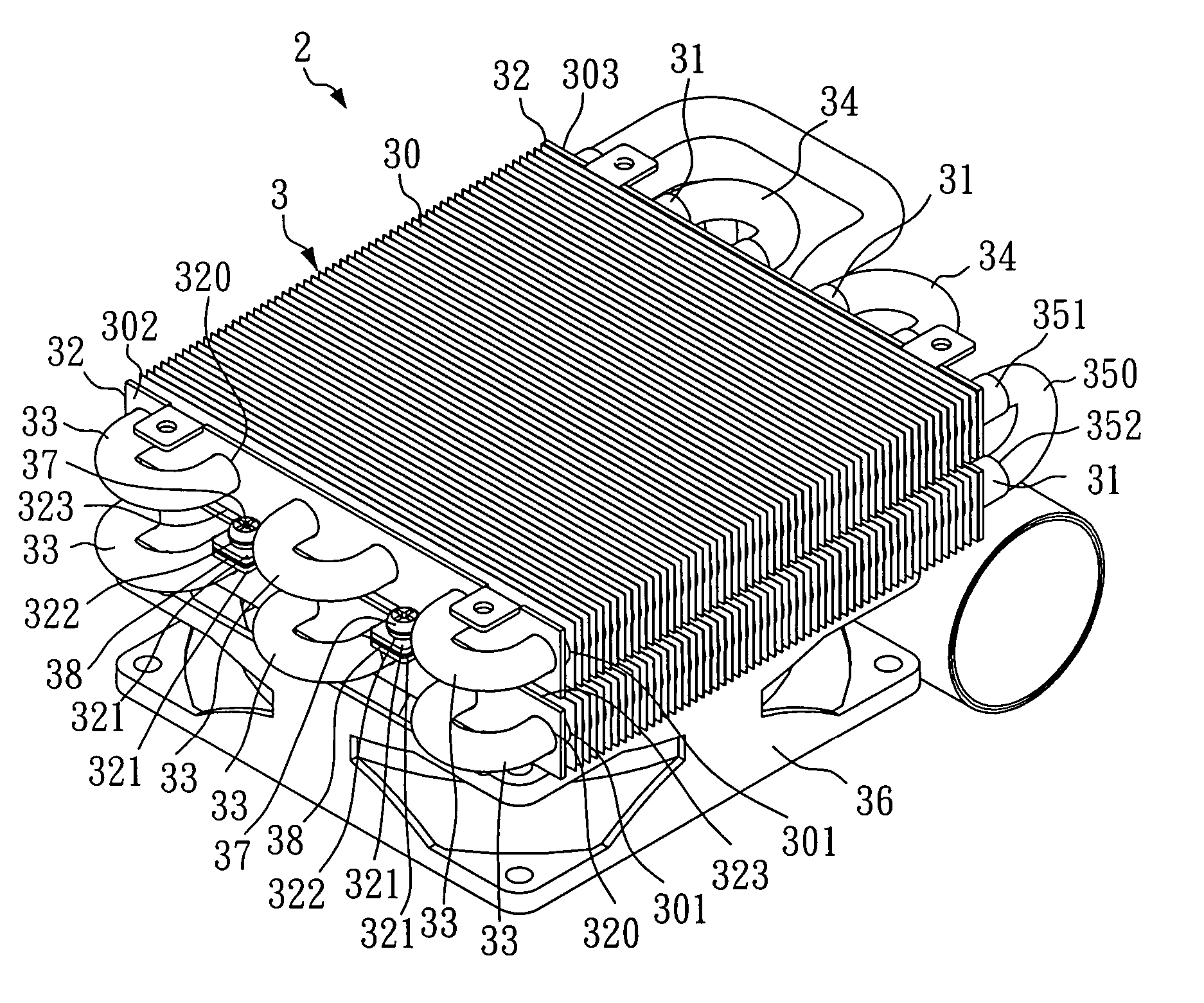
[0017] Referring to FIGS. 3-5, a modularized cooler 2 in accordance with the present invention is shown comprised of two heat radiator modules 3, a connecting tube 350, and a fan 36.

[0018] The two heat radiator modules 3 are arranged in a stack, each comprising a plurality of radiation fins 30, and a plurality of heat-exchange tubes 31, two locating plates 32, a plurality of first bends 33, and a plurality of second bends 34. According to this embodiment, the radiation fins 30 are arranged in parallel and spaced from one another in longitudinal direction at a predetermined pitch, each having a plurality of through holes 301 extending in longitudinal direction. The heat-exchange tubes 31 are straight tubes respectively longitudinally mounted inside the through holes 301 of the radiation fins 30 and arranged in parallel.

[0019] Further, the two locating plates 32 are respectively fastened to the first outer side 302 and second outer side 303 of the set of radiation fins 30 of the res...


PUM


Abstract

A modularized cooler includes the at least two heat radiator modules arranged in a stack, each heat radiator module having a set of radiation fins, heat-exchange tubes arranged in parallel and surrounded by the radiation fins, two locating plates holding the heat-exchange tubes in place, and a plurality of first bends and second bends respectively connected between every two adjacent heat-exchange tubes at two sides of the radiation fins and forming with the heat-exchange tubes a continuously S-shaped piping having an inlet and an outlet, and at least one connecting tubes that connect the S-shaped pipings of the heat radiator modules in series.

Description

BACKGROUND OF THE INVENTION [0001] 1. Field of the Invention [0002] The present invention relates to a cooler for cooling an electronic device and more particularly, to a modularized cooler. [0003] 2. Description of Related Art [0004]FIG. 1 is a rear side view of a fluid cooling type cooler for computer according to the prior art. According to this design, the heat-exchange tubes 10 of the cooler are arranged in a staggered manner that imparts a barrier to the flowing of currents of air caused by the fan 11, thereby resulting in a high wind resistance between the fan 11 and the heat radiator 1. The staggered arrangement of the heat-exchange tubes 10 results in a bulky size of the heat radiator 1. [0005] Referring to FIG. 2, the heat-exchange tubes 10 of the heat radiator 1 are fixedly mounted inside the radiation fins 12 and arranged into two rows that are spaced from the fan 11 at different distances, thereby defining a hot flow zone 13 and a sub-hot flow zone 14 that cause direct ...

Claims


Application Information

Patent Timeline
IPC IPC(8): F28D1/04F28D1/00F28D1/047F28F1/32F28F9/26G06F1/20H01L23/473H05K7/20
CPCF28D1/0477F28D2021/0031F28F1/32F28F9/262G06F1/20H01L2924/0002H01L23/473H01L2924/00
Inventor HUANG, JUNG-FONGHUANG, CHIH-CHIEN
Owner FORWARD ELECTRONICS CO LTD
Why Eureka
Try Eureka