

Photovoltaic module
- Summary
- Abstract
- Description
- Claims
- Application Information
AI Technical Summary
Benefits of technology
Problems solved by technology
Method used
Image

Examples
first embodiment
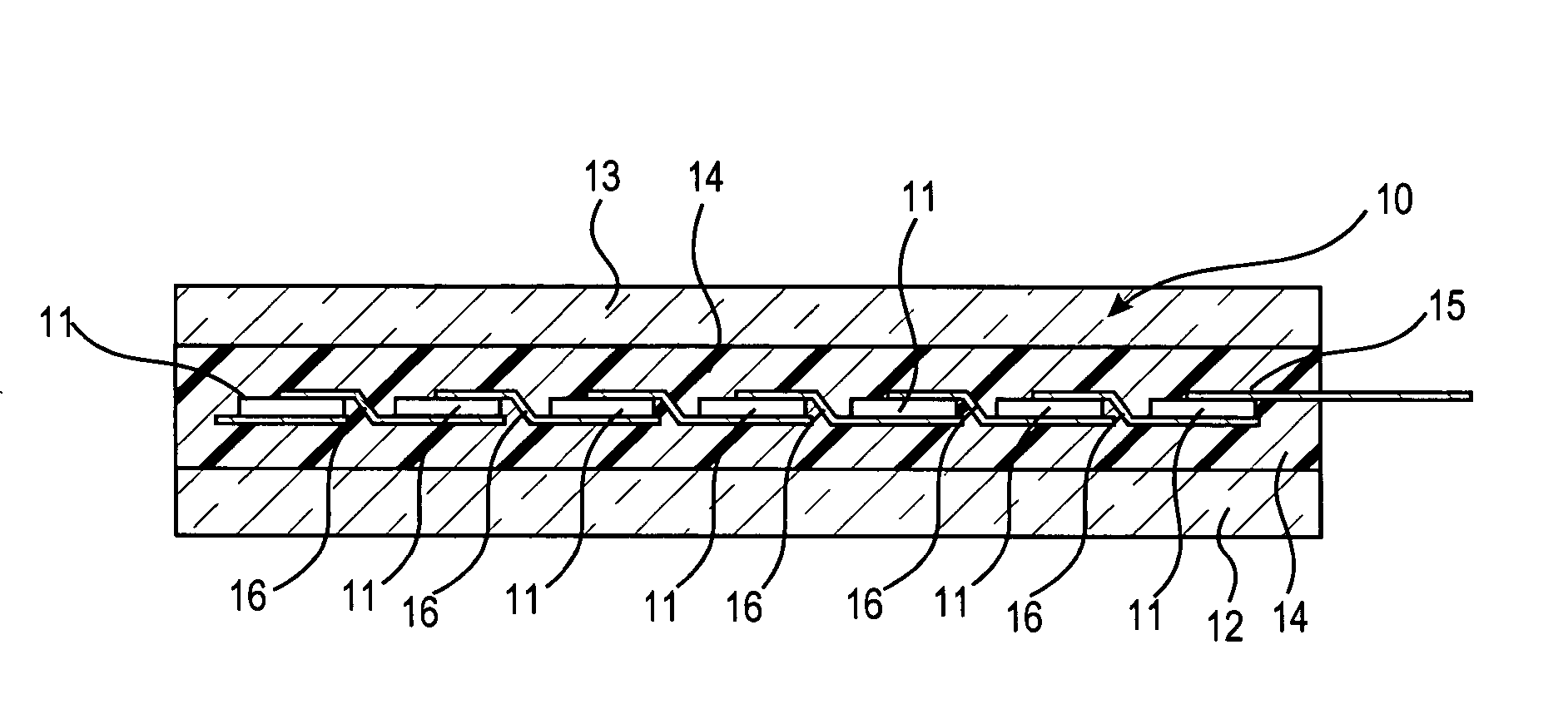
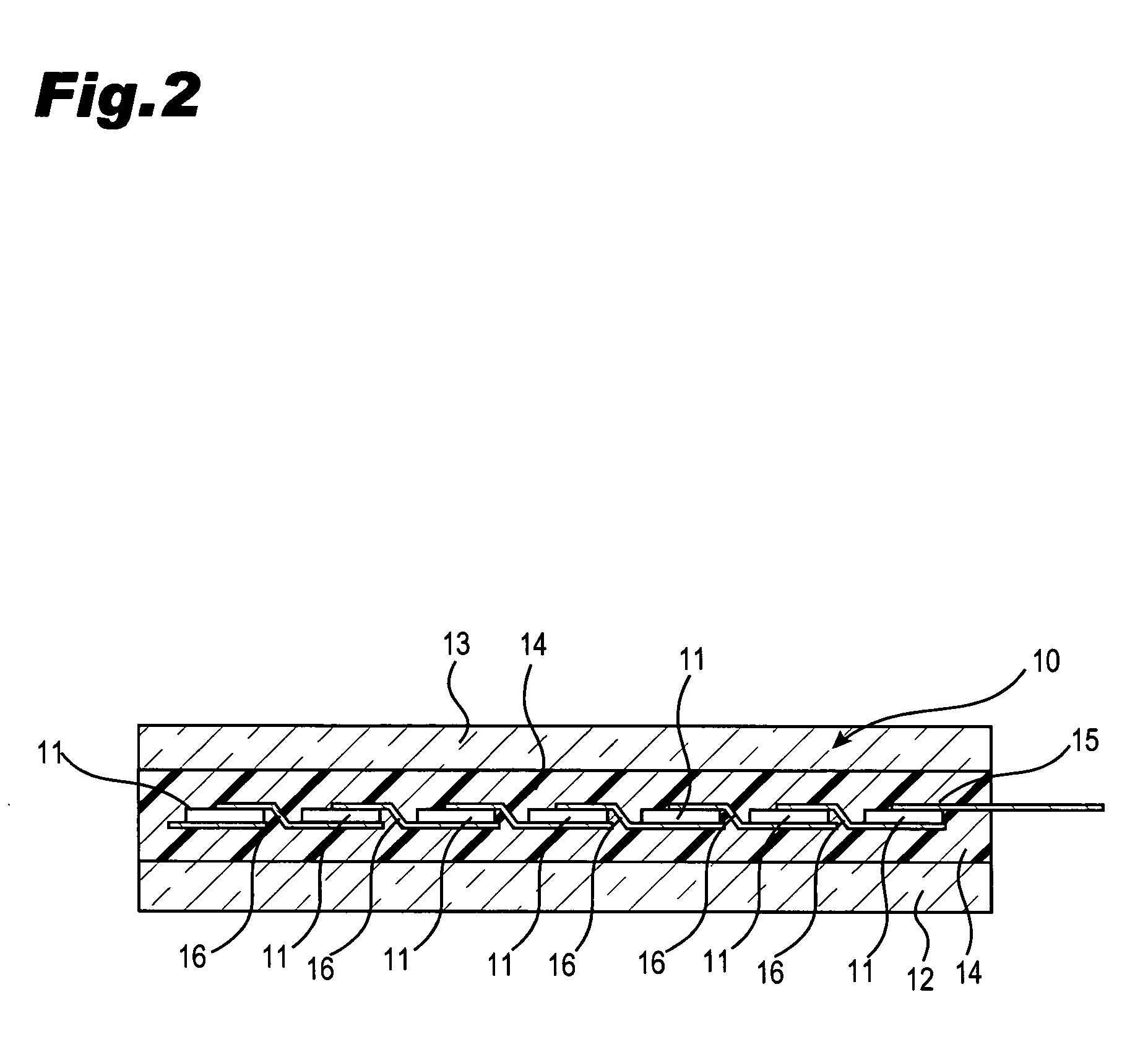
[0065] In the first embodiment, the light-receiving side light-transmitting insulative substrate 12 and the rear surface side light-transmitting insulative substrate 13 have the same dimensions. Each of the substrates 12 and 13 is made of low iron tempered glass with an outer dimension of 980 mm×1500 mm for example.
[0066] Various types of solar cells are available for the solar cell 11 such as crystalline-type, amorphous-type and the like. Recently, a solar cell which reduces loss of power generation at defective areas on its surface to realize high power generation has been in the spotlight. A substantially i-type amorphous silicon layer without dopant is interposed between a crystalline substrate and a p-type amorphous silicon layer, and between a crystalline substrate and an n-type amorphous silicon layer so as to improve interface characteristics. These solar cells 11 are connected in series or parallel to generate a specified output such as 200 W from the photovoltaic submodule...
third embodiment
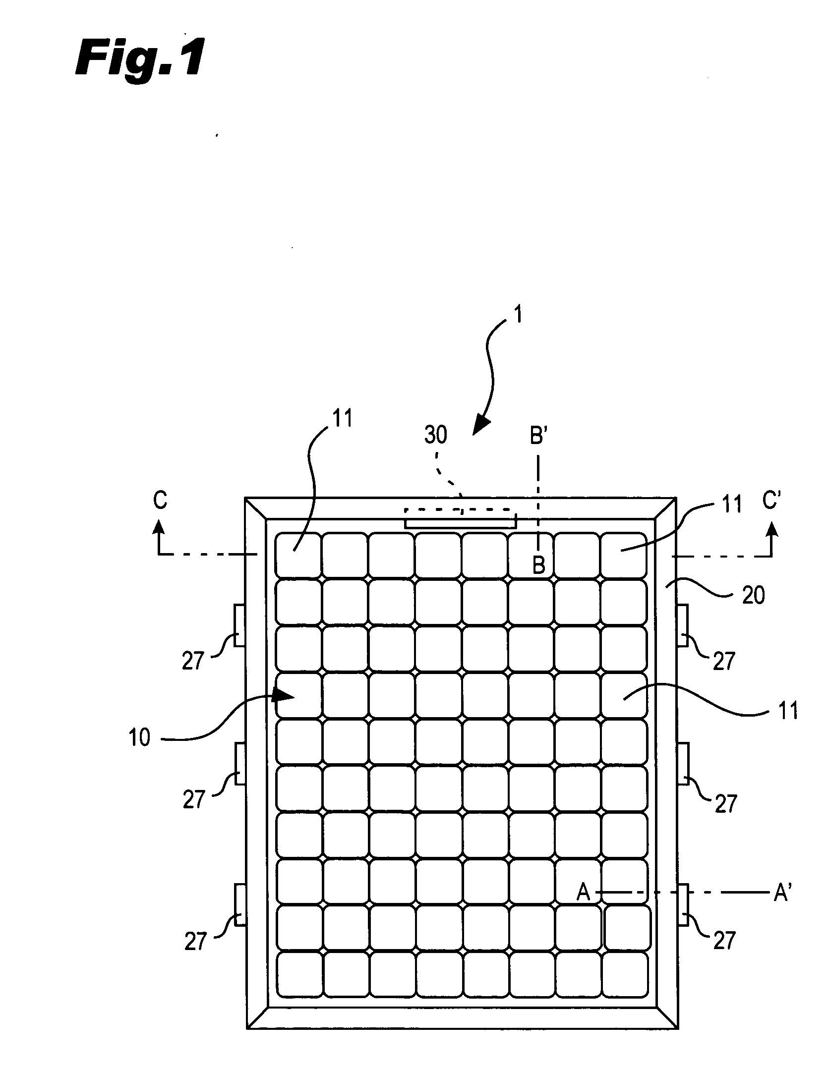
[0101] As illustrated in FIG. 16, the terminal box 30 is attached near to the edge of the rear surface side light-transmitting insulative substrate 13 of the photovoltaic submodule 10. Part of the terminal box 30 is housed in the hollow of the main body 21 through the opening 28 provided to the outer frame 20. The photovoltaic submodule 10 is set in the fitting part 22 with the upright part 38 of the terminal box 30 abutting on the inner wall of the fitting part 22. In the third embodiment, the upright part 38 is formed in such a height as to reach to the inner wall which contacts with the front surface of glass 12 of the fitting part 22. The upright part 38 is located between the inner wall of the fitting part 22 and the photovoltaic submodule 10, so that the edge of the photovoltaic submodule 10 does not contact the outer frame 20 made of metal. The photovoltaic submodule 10 is set in the fitting part 22 in such a manner that a space A through which the connecting lead 15 is guide...
fourth embodiment
[0105] Part of the terminal box 30 is housed in the hollow of the main body 21 through the opening 28 provided to the outer frame 20. The photovoltaic submodule 10 is set in the fitting part 22 with the upright part 38 of the terminal box 30 abutting on the inner wall of the fitting part 22. In the fourth embodiment, the upright part 38 is formed in such a height as to reach to the inner wall at the light receiving side of the fitting part 22. The upright part 38 is located between the inner wall of the fitting part 22 and the photovoltaic submodule 10, so that the edge of the photovoltaic submodule 10 does not contact the outer frame 20 made of metal. The photovoltaic submodule 10 is set in the fitting part 22 in such a manner that a space A through which the connecting lead 15 can be guided is maintained between the upright part 38 and the edge of the photovoltaic submodule 10.
[0106] As described above, the connecting lead 15 can be guided to the inside of the terminal box 30 thro...
PUM
 Abstract
Description
Claims
Application Information