Image stabilizer

a stabilizer and image technology, applied in the field of art image stabilizers, can solve the problems of reducing the resolution of the telescope, deteriorating the image, and blurring of images, so as to reduce the production cost and the dimensions of the device, reduce the design constraints of the image stabilizer, and reduce the production cost and the effect of the suspension system

Active Publication Date: 2014-04-03
KAMAKURA KOKI
View PDF3 Cites 16 Cited by
  • Summary
  • Abstract
  • Description
  • Claims
  • Application Information

AI Technical Summary

Benefits of technology

[0030]The image stabilizer according to the present invention is capable of compensating for deterioration in the quality of observed images caused by hands movement that acts on the optical device such as a monocular or binoculars. Furthermore, there is a little restriction on the design of the image stabilizer. The mechanism for driving the gimbal suspension system is simple, which reduces the production cost and the dimensions of the device. Thus the image stabilizer is applicable to other optical devices such as laser range-finding devices, and it is usable in a wide range of fields.

Problems solved by technology

As a result, the quality of the image of the observed object, or the optical image, may deteriorate in such a manner that the image is blurred, or the resolution of the telescope becomes apparently lowered.
Even if the magnitude of the vibrations transmitted to the telescope, such as monoculars and binoculars, is small, the optical image that makes an appeal to the eyes deteriorates in the end.
Thus, as the magnifying power of a telescope becomes large, changes in the angle of a beam emitted by an observed object to the optical axis of the telescope and deterioration in the quality of the observed image, caused by factors such as vibrations, become unignorable.
On the other hand, this device has a serious problem: When this image-stabilizing optical device attends to, for example, lateral movements of the optical device, the prism holder is pivoted around the middle position between the erecting prism in the left optical system and the erecting prism in the right optical system, or the vertical axis running through the intersection O in FIGS. 1 and 4 of patent document 1.
This difference results in a difference between how an observed object is seen through the right optical system and how the same object is seen through the left optical system.
This image stabilizer does not resolve the difference between how an observed object is seen through the right optical system and how the same object is seen through the left optical system.

Method used


Image

  • Image stabilizer
  • Image stabilizer
  • Image stabilizer

Examples


Embodiment Construction

Problems to be Solved by the Invention

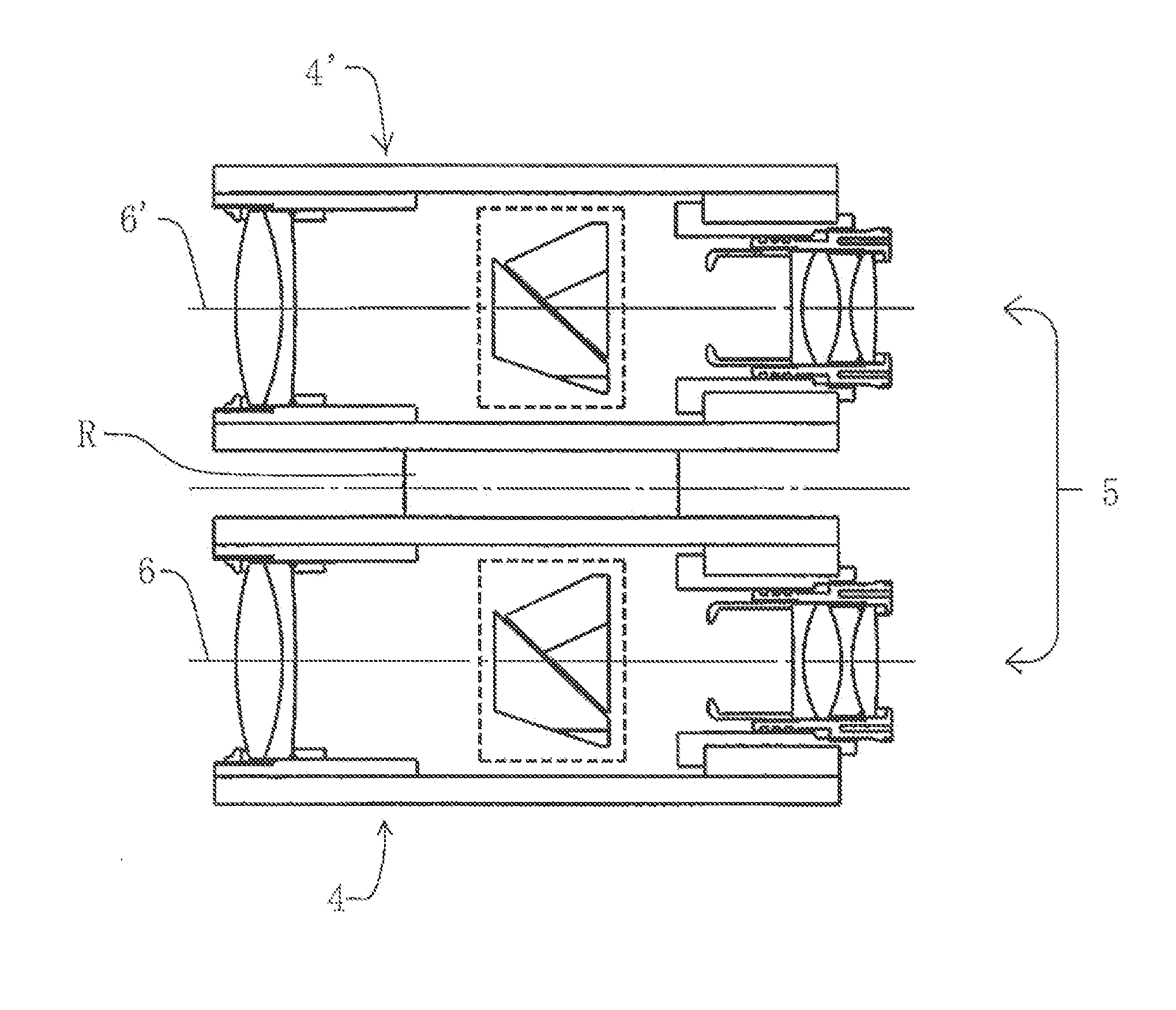
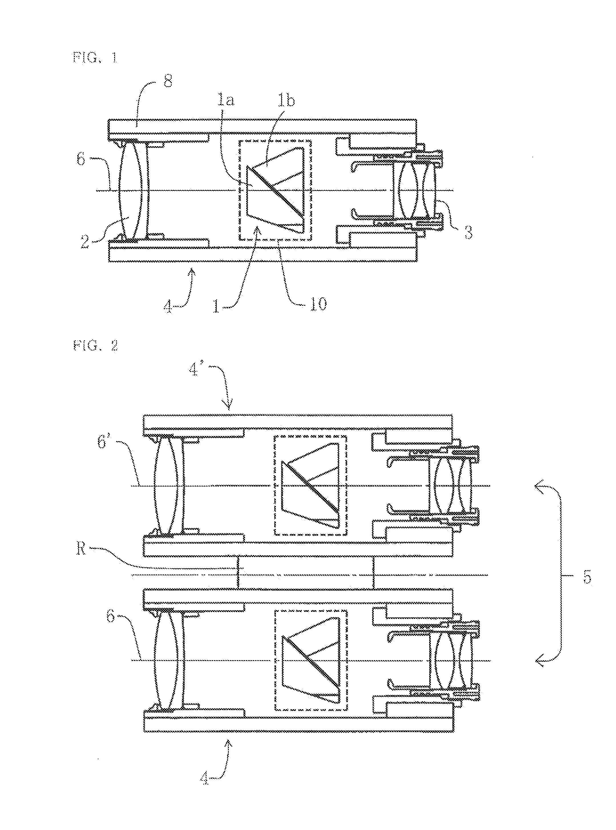
[0016]An objective of the present invention is to provide a small, light-weight, and inexpensive actuator for driving a gimbal suspension device which is one of the main elements of an image stabilizer to compensate for deterioration in the quality of an observed image caused by hands movement of the user, the image stabilizer applicable to a monocular or binocular optical system that comprises an erecting prism placed between an objective lens and an eyepiece, wherein the gimbal suspension system rotates the erecting prism about two orthogonal axes included in a plane that is perpendicular to the optical axis of the monocular or binocular optical system.

[0017]In more detail, the objective of the present invention is to provide an image stabilizer for a monocular and binoculars capable of compensating for deterioration in observed images, which is generated by changes in the angle of a beam emitted by an observed object to the optical axis of an...


PUM


Abstract

An image stabilizer applicable to a monocular or binocular optical system. The stabilizer includes an erecting prism placed between an objective lens and an eyepiece to compensate for deterioration in a quality of an observed image caused by hands movement. The image stabilizer includes a gimbal suspension system having pivot shafts respectively extending to left and right sides of the optical axis of the optical system. The pivot shafts have a common pivot axis perpendicular to the optical axis. The gimbal suspension system has an erecting-prism holder supported by the pivot shafts, an angular velocity detector for detecting an angular displacement of the erecting prism, and a voice coil motor for pivoting the erecting-prism holder.

Description

FIELD OF INVENTION[0001]The present invention relates to art image stabilizer for a monocular and binoculars capable of compensating for deterioration in observed images, which is generated by changes in the angle of a beam emitted by an observed object to the optical axis of an optical device, which is caused by hands movement, due typically to movements of the optical device, such as a monocular or binoculars.BACKGROUND OF THE INVENTION[0002]When the user operates a telescope for optical observation, typical examples of which may include monoculars and binoculars, in order to watch an object, holding the device with her / his hands especially in an airplane or in a train, vibrations from the airplane or the train are brought to bear on the case of the telescope, which causes hands movement of the user. The hands movement causes a change in the angle of a beam emitted by the observed object to the optical axis of the telescope. As a result, the quality of the image of the observed ob...

Claims


Application Information

Patent Timeline
Patent Type & Authority Applications(United States)
IPC IPC(8): G02B27/64
CPCG02B27/646
Inventor ANDO, KUNIOKATO, MASASHIITOH, HARUO
Owner KAMAKURA KOKI
Why Eureka
Try Eureka