Apparatus and methods for locking resonating frequency of a miniature system

a miniature system and resonating frequency technology, applied in the field of microelectromechanical systems, can solve the problems of not recognizing the materiality of such publications and patent documents to patentability, and achieve the effect of improving performance and reducing the dimension and/or cost of devices

Active Publication Date: 2014-08-07
MARADIN
View PDF2 Cites 12 Cited by
  • Summary
  • Abstract
  • Description
  • Claims
  • Application Information

AI Technical Summary

Benefits of technology

[0024]Certain embodiments of the invention presented here include a new architecture that is based on a novel technology to present a new system and method for frequency control and resonance locking of mechanical devices. This novel architecture provides improved performance over known state-of-the-art technologies and / or reduces dimension and / or cost of devices.

Problems solved by technology

Materiality of such publications and patent documents to patentability is not conceded.

Method used


Image

  • Apparatus and methods for locking resonating frequency of a miniature system
  • Apparatus and methods for locking resonating frequency of a miniature system
  • Apparatus and methods for locking resonating frequency of a miniature system

Examples


first embodiment

[0094]FIG. 9b is a detailed block diagram illustration of the driver and controller unit of FIG. 9a typically including some or all of a High Voltage Pulse Generator (HVPG), a mechanical device (XMEMS), an electronic unit that manipulates the capacitive signals (XSense) and a PLL.

second embodiment

[0095]FIG. 9c is a detailed block diagram illustration of the driver and controller of FIG. 9a typically including some or all of a High Voltage Pulse Generator (HVPG), a mechanical device (XMEMS), an electronic unit that manipulates the capacitive signals (XSense), a Sample and Compare unit and a Digital Logic unit.

[0096]FIG. 10 is a diagram of the signals used to drive and sense the mechanical system, as shown in FIG. 9b.

[0097]FIGS. 11a-11b depict the electrical signals that are used to drive and sense the mechanical system of FIG. 9c.

[0098]FIG. 12 is a simplified flowchart illustration of a first example method for monitoring changes in the resonance frequency of a MEMS (Micro Electro Mechanical System).

[0099]FIGS. 13a-13b, taken together, form a simplified flowchart illustration of a second example method for monitoring changes in the resonance frequency of a MEMS (Micro Electro Mechanical System).

DETAILED DESCRIPTION OF CERTAIN EMBODIMENTS

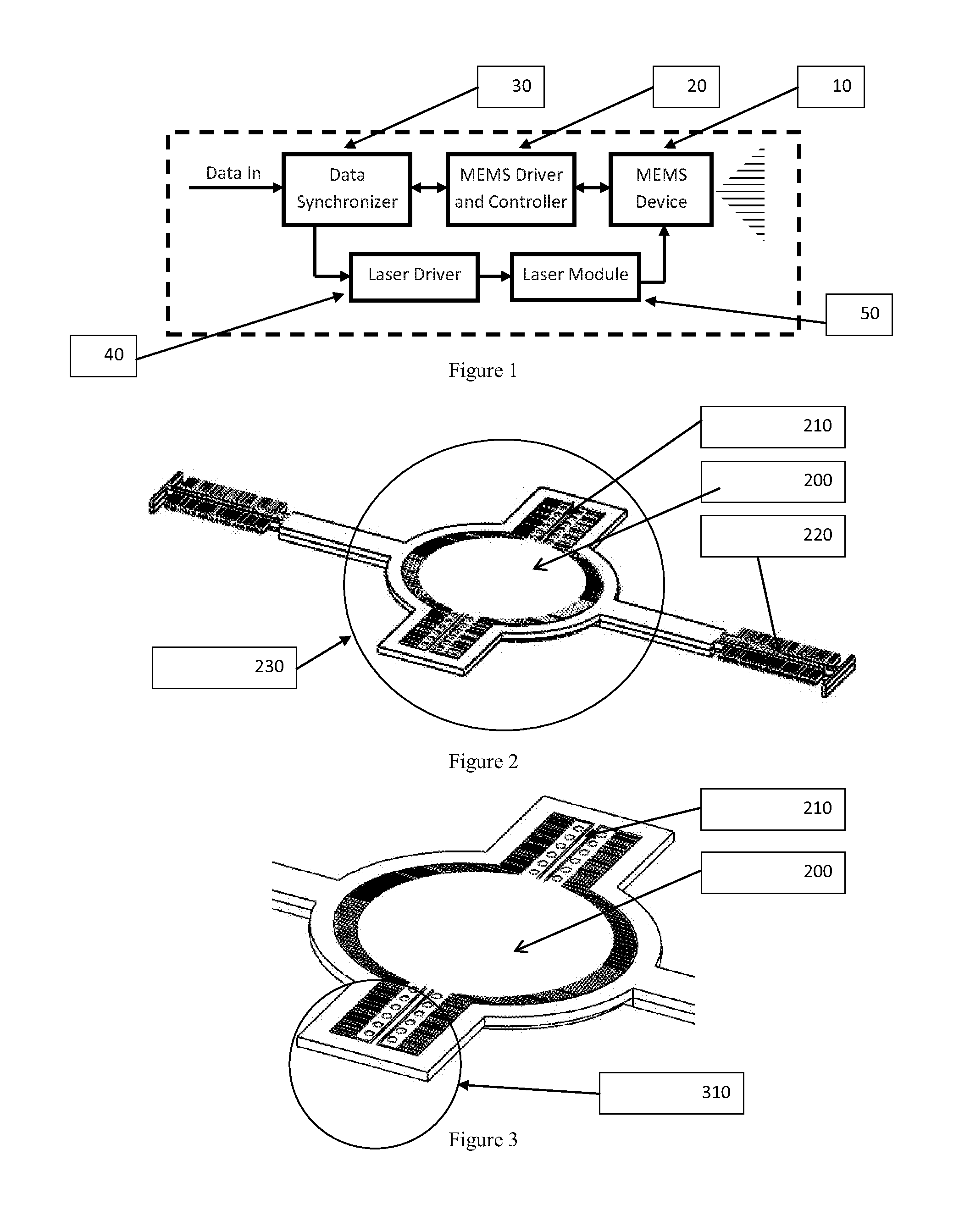
[0100]FIG. 1 is a simplified block d...


PUM


Abstract

A resonance locking system for a pico-projector, the system comprising a resonance frequency sensor operative for sensing change in resonance frequency of a miniature mechanical device (10) including a moving mirror assembly having a driving frequency, by comparing a current resonance frequency to a reference; and a feedback loop changing at least one aspect of use of the miniature moving mirror assembly responsive to a current value of the resonance frequency measured by the sensor.

Description

REFERENCE TO CO-PENDING APPLICATIONS[0001]Priority is claimed from U.S. Provisional Patent Application No. 61 / 530,977, entitled “A mechanism for resonating frequency lock” and filed Sep. 4, 2011.FIELD OF THIS DISCLOSURE[0002]The present invention relates generally to Micro-Electro-Mechanical Systems.BACKGROUND FOR THIS DISCLOSURE[0003]Conventional technology constituting background to certain embodiments of the present invention is described in the following publications, inter alia:US 2011 / 0001888 A1 to Brownet al (assigned to Microvision)US 2008 / 0158631 A1 to Davis et al (assigned to Microvision)US 2005 / 0280879 A1 to Gibson (assigned to Microvision)MOEMS translatory actuator characterization, position encoding and closed-loop controlM. Lenzhofer • A. Tortschanoff • A. Frank •T. Sandner • H. Schenk • M. Kraft • A. KendaMicrosyst Technol (2010) 16:901-907 [0004]DOI 10.1007 / s00542-010-1029-5US 2011 / 0181931 A1 to Luft et al (assigned to BTendo)US 2011 / 0109951 A1 to Goren et al (assign...

Claims


Application Information

Patent Timeline
Patent Type & Authority Applications(United States)
IPC IPC(8): G03B21/28
CPCG03B21/28G09G3/025G09G3/346G09G2310/08G02B26/0841
Inventor NAFTALI, MATANKEYDAR, EYTANLANGER, TALHORNSTEIN, SHARON
Owner MARADIN
Why Eureka
Try Eureka