Soldering iron and method of manufacturing same

a technology of soldering iron and soldering iron plate, which is applied in the direction of ohmic-resistance heating, manufacturing tools, and soldering apparatus, etc., can solve the problems of heat being transmitted to the grip portion of the soldering iron plate, electrical shortening or breaking of adjacent wires, etc., and achieves rapid heating, small size, and increased heating per unit volume

Active Publication Date: 2006-05-25
TAIYO ELECTRIC IND
View PDF24 Cites 27 Cited by
  • Summary
  • Abstract
  • Description
  • Claims
  • Application Information

AI Technical Summary

Benefits of technology

[0020] In this case, the wire that generates heat by its resistance is insulated from mutual electrical contact by the insulating oxide film. Electrical shorting is thereby avoided even if the adjacent turns of the wire make mutual contact, thus allowing the coiled wire to be disposed with the spacing therebetween narrowed. In addition, electrical problems such as wire breakage are also easily avoided with the insulating oxide film. Moreover, since the temperature sensor is provided abutting against the inner periphery of the insertion fit recess portion, the temperature of the soldering tip may be desirably measured.
[0021] Accordingly, in the heater built in the soldering tip manufactured thus, the spacing between the adjacent turns of the wire disposed in a coil shape may be made still smaller. This enables the size of the heater to be constituted small, so that the soldering tip may be constituted extremely small. In addition, since the spacing between the adjacent turns of the wire is narrowed, the amount of heating per unit volume also increases, and so the soldering tip...

Problems solved by technology

For that reason, there has been the problem of adjacent wires electrically shorting or breaking by contact.
Moreover, increasing the spa...

Method used


Image

  • Soldering iron and method of manufacturing same
  • Soldering iron and method of manufacturing same
  • Soldering iron and method of manufacturing same

Examples


Embodiment Construction

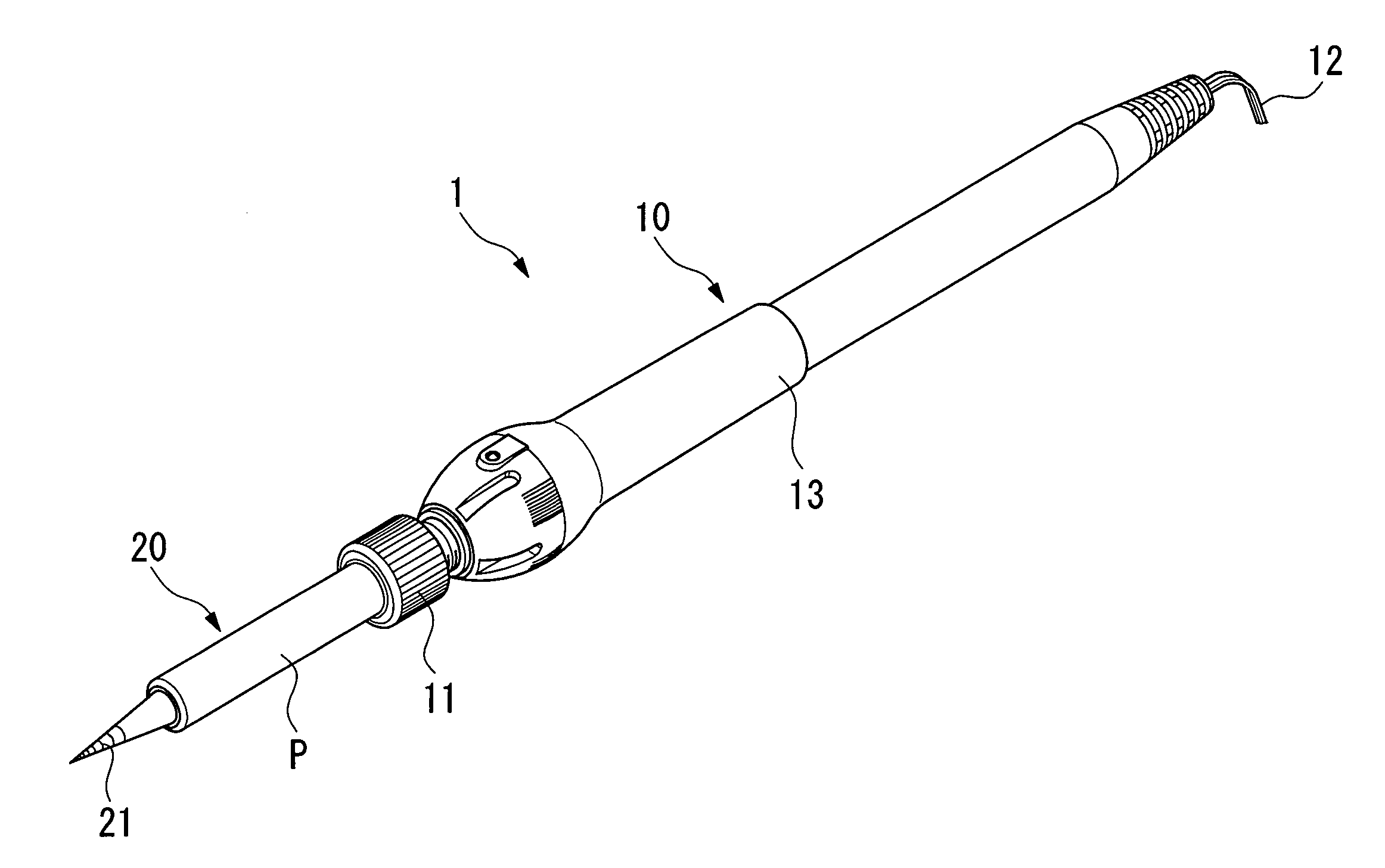
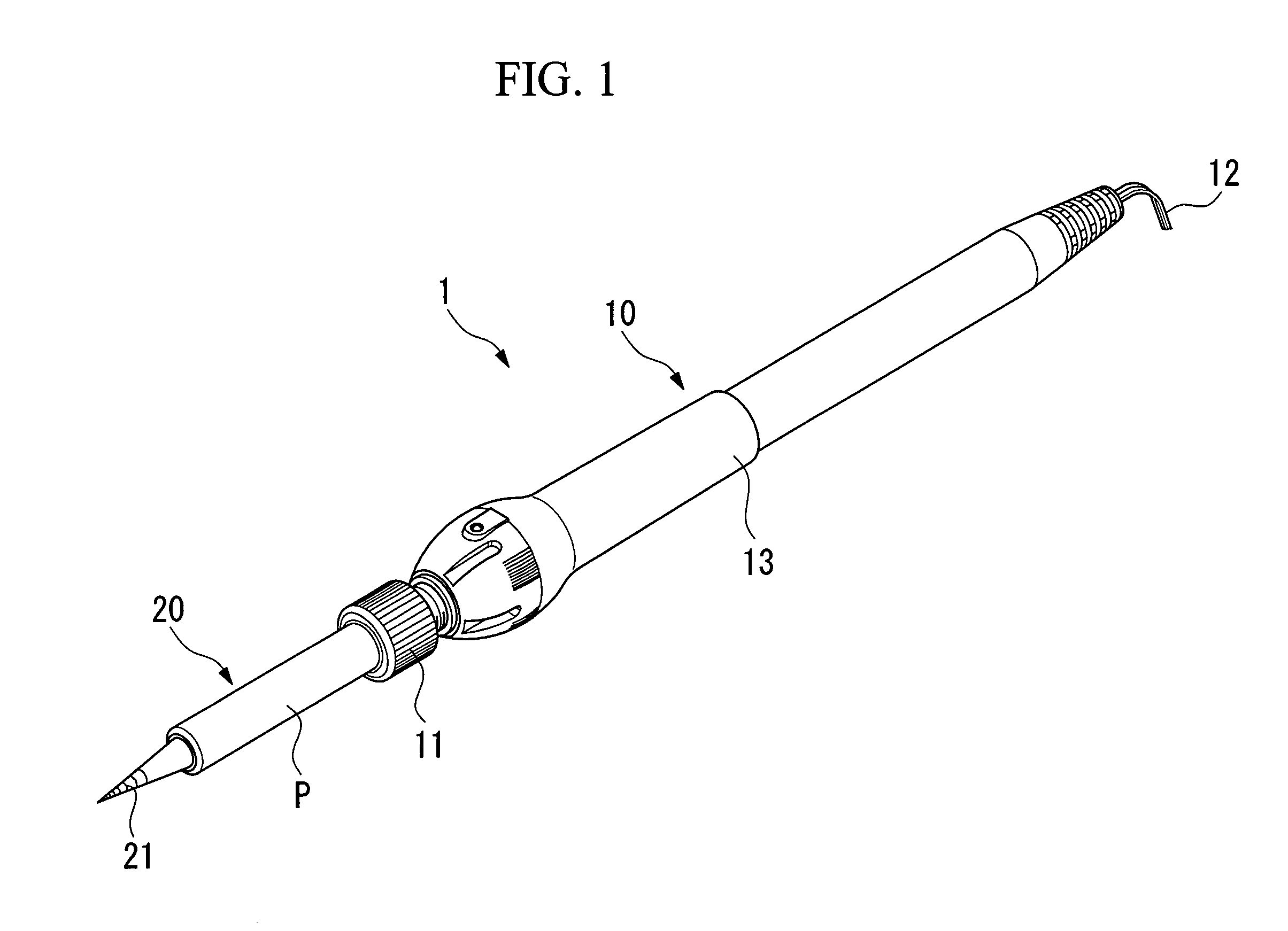
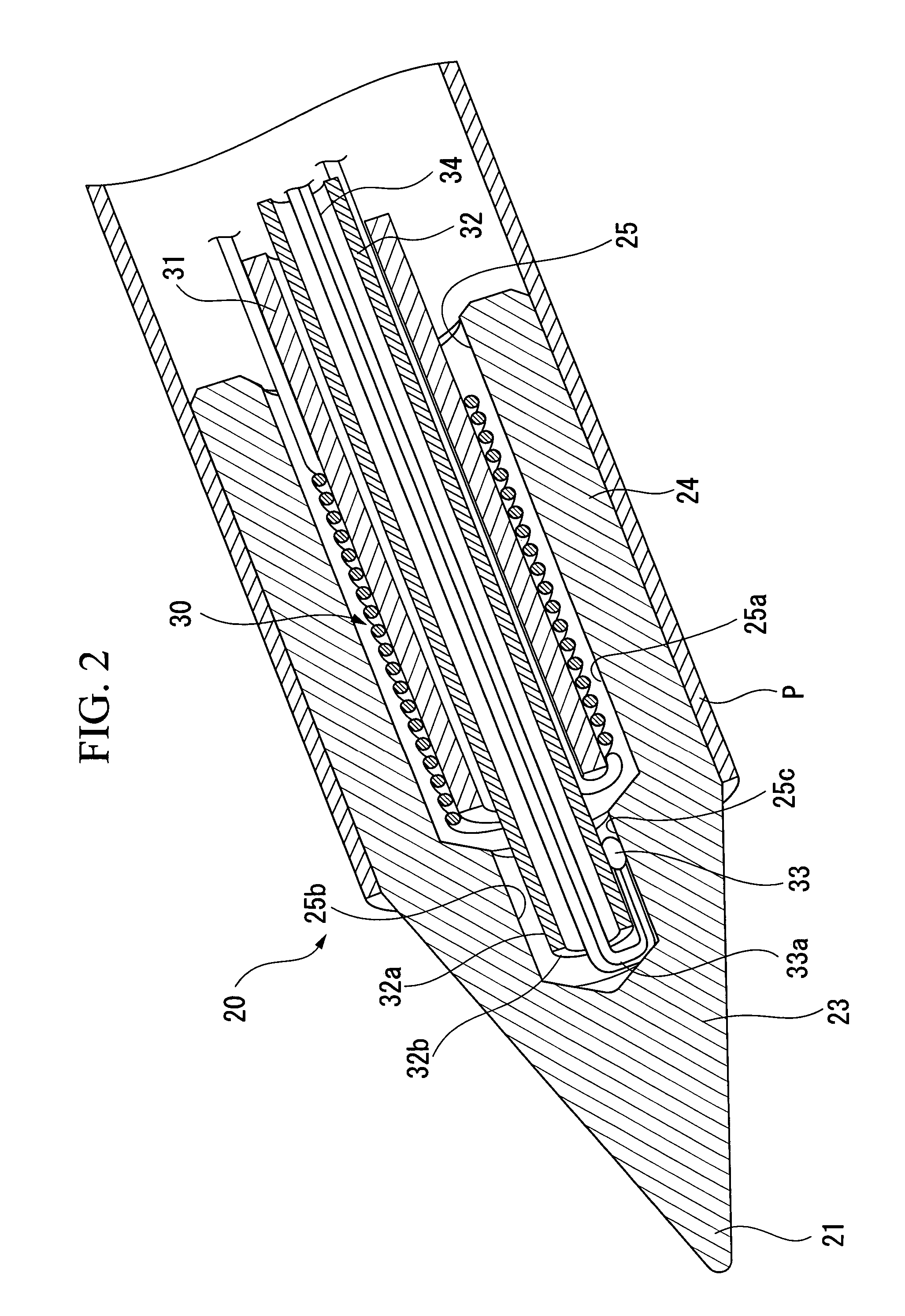
[0026] Below, the embodiment of the soldering iron of the present invention and the manufacturing method thereof are explained referring to the drawings. FIG. 1 is a perspective view of the soldering iron of the present invention, FIG. 2 is a cross-sectional perspective view of the soldering tip, and FIG. 3 is a schematic cross-sectional view of the coil diameter direction of the heater.

[0027] A soldering iron 1 shown in FIG. 1 melts solder at a distal end thereof, and is used for the purpose of soldering or removing attached solder. The soldering iron 1, roughly divided, has a soldering tip 20 equipped with a bit 21 for melting solder, and a body (holding shaft) 10 connected with a proximal end of the soldering tip 20.

[0028] The soldering tip 20 is joined to the distal end of the body 10 via an engaging member 11 at the distal end thereof, and a cord 12 equipped with a plug (not shown) for connection to a power supply is provided at the proximal end of the body 10. The middle par...


PUM

PropertyMeasurementUnit
Temperatureaaaaaaaaaa
Timeaaaaaaaaaa
Temperatureaaaaaaaaaa

Abstract

A soldering iron provided with a soldering tip that melts solder at a distal end, having inside said soldering tip a substantially cylindrical insertion fit recess portion extending from a proximal end of the soldering tip to the distal end, opening at the proximal end, and a heater formed into a coil shape and whose surface is covered with an insulating oxide film being fittingly inserted into the insertion fit recess portion.

Description

BACKGROUND OF THE INVENTION [0001] 1. Field of the Invention [0002] This invention relates to a soldering iron and a method of manufacturing the soldering iron. [0003] Priority is claimed on Japanese Patent Application No. 2004-340157, filed Nov. 25, 2004, the content of which is incorporated herein by reference. [0004] 2. Description of Related Art [0005] Soldering iron tips have been provided in which a thermally conductive material is formed in the shape of a cone with a heater being housed therein (refer to Japanese Unexamined Application, First Publication No. 2004-17060). The heater generally includes a comparatively high-resistance wire wound into the shape of a coil. [0006] In recent surface-mount technology involving the soldering of extremely small LSIs and the like onto a substrate, parts to be soldered and parts not to be fused are disposed together within very close proximity. For this reason, there have been proposed soldering irons constructed to be extremely small (h...

Claims


Application Information

Patent Timeline
IPC IPC(8): H05B3/42B23K3/00
CPCB23K3/0338Y10T29/49B23K3/0369B23K3/033B23K3/053B23K3/08
Inventor SHIGEKAWA, TOMOHIRO
Owner TAIYO ELECTRIC IND
Why Eureka
Try Eureka