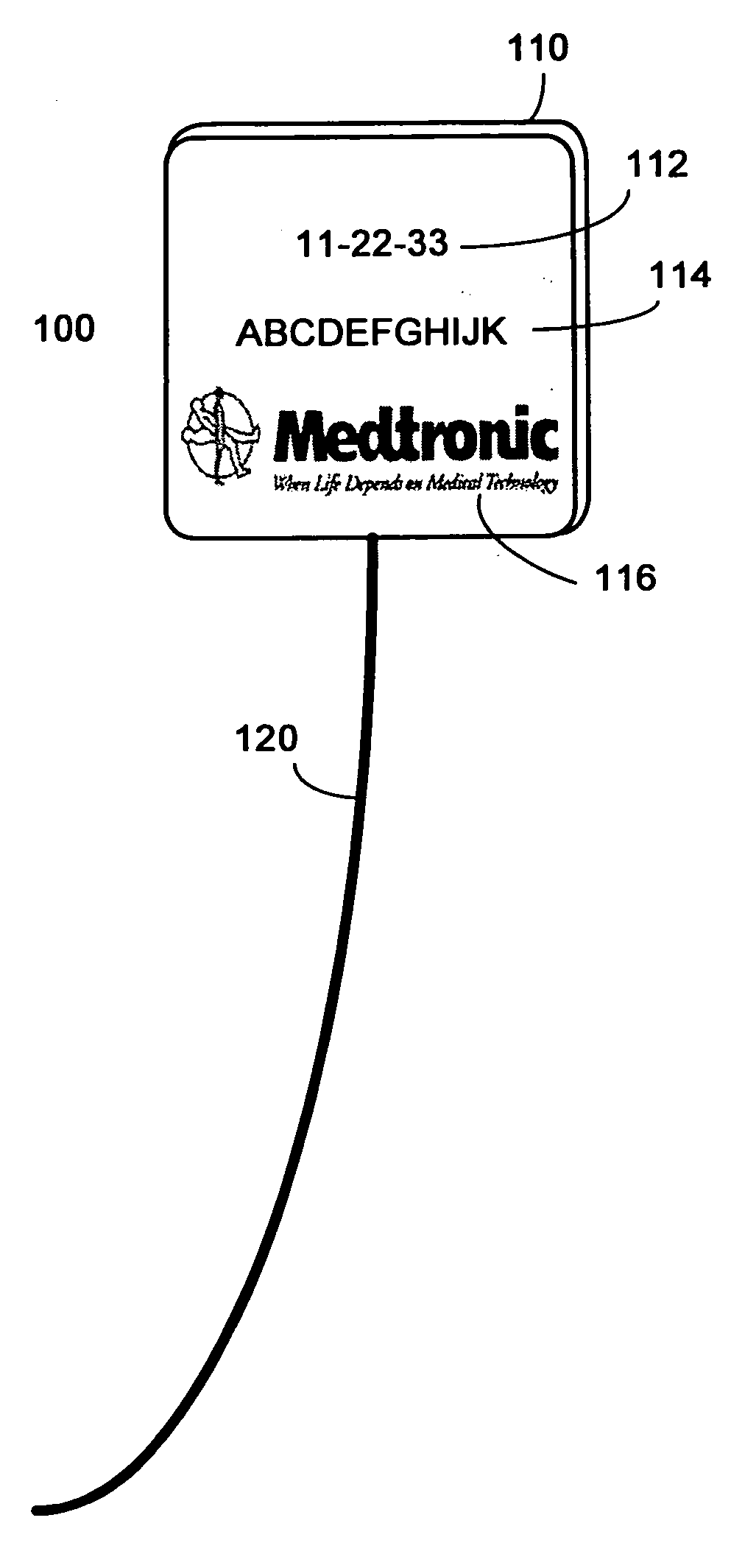
Twist-tie RFID tag

a technology of rfid tags and twist-tie rings, which is applied in the field of rf inventorying techniques, can solve the problems of limited information that the symbols can contain, inductively coupled tags remain relatively expensive, and limited bar codes in size, so as to achieve cost savings, transparent operation, and save design and resources.

Inactive Publication Date: 2006-05-25
WARSAW ORTHOPEDIC INC
View PDF25 Cites 66 Cited by
  • Summary
  • Abstract
  • Description
  • Claims
  • Application Information

AI Technical Summary

Benefits of technology

[0015] There exists a need for an RFID tag and attachment system that ameliorates some of all of the above-noted deficiencies of previous RFID tag and attachment systems. Embodiments of the present invention mitigate or solve the above-identified limitations, as well as other unspecified deficiencies. A number of advantages associated with various embodiments of the present invention will be readily evident to those skilled in the art, including economy of design and resources, transparent operation, cost savings, etc.

Problems solved by technology

Despite advances in silicon manufacturing processes, inductively coupled tags have remained relatively expensive due to the coil antenna and the manufacturing process required to wind the coil around the surface of the tag.
For example, bar codes are limited in size by resolution limitations of bar code scanners, and the amount of information that the symbols can contain is limited by the physical space constraints of the label.
Therefore, some objects may be unable to accommodate bar code labels because of their size and physical configuration.
As labels become worn or damaged, they can no longer be read with the bar code scanner.
Also, because a person operating the bar code scanner must physically orient either the scanner or the product to achieve line of sight on each item being scanned, items must be scanned one at a time resulting in prolonged scan time.
A problem of RFID tags, which also is common to bar code tags is that it can be difficult to securely attach the tags to various goods and products.
However, in some applications, a paper tag may not hold up to the rigors of the application environment.
Over time, a paper RFID tag would not provide reliable performance under these harsh conditions.
While making the tag enclosure more rugged protects the internal components of the tag, this still does not solve the problem of keeping the tag securely attached, particularly in harsh environments.
This presents at least two problems for the application of tags exposed to harsh environments.
First, adhesives will break down and lose their adhesive property when they are exposed to heat and moisture.
This limits their usage to dry “friendly” environments.
Second, adhesives require a flat surface on which to mount the RFID tags.
This precludes the mounting of tags onto devices, equipments, or containers that do not have a flat surface of sufficient dimensions.
Furthermore, many items do not have geometrically shaped portions sufficiently large to accommodate such a substrate based tag.
Thus, for at least these reasons, adhesives do not provide a robust solution for attaching RFID tags.
However, a problem with this solution is that the band width will preclude application of the bracelet to small items.

Method used


Image

  • Twist-tie RFID tag
  • Twist-tie RFID tag
  • Twist-tie RFID tag

Examples


Embodiment Construction

[0027] The following description is intended to convey a thorough understanding of the invention by providing specific embodiments and details involving RFID identification systems. It is understood, however, that the invention is not limited to these specific embodiments and details, which are exemplary only. It is further understood that one possessing ordinary skill in the art, in light of known systems and methods, would appreciate the use of the invention for its intended purposes and benefits in any number of alternative embodiments, depending upon specific design and other needs.

[0028] Throughout this description, the expression “RFID transponder tag” will be given broad meaning including, but not limited to, any active or passive type of electronic data storage device that is wirelessly activated in the presence of a radio frequency (RF) field including any currently available inductively coupled tags, capacitively coupled tags and even future RF-type tags not yet available...


PUM


Abstract

An RFID tag that incorporates at least one integral or permanently attached twist-tie fastener for easy attachment, detachment and reattachment to various items to be inventoried is provided. The RFID tag is included at least partially in a protective housing to permit it to be utilized in hostile environments. The twist-tie portion is attached to the tag and preferably is constructed of a braided or single strand wire. One or more visual indicia also may be printed on the face of the protective housing.

Description

FIELD OF THE INVENTION [0001] The invention generally relates to RF inventorying techniques and more specifically to a new and useful reusable twist-tie RFID transponder tag for easy attachment, detachment and reattachment to a variety of different shaped devices and equipment. The RFID transponder tag can be applied, in particular, to medical and surgical devices and equipment. BACKGROUND OF THE INVENTION AND DESCRIPTION OF RELATED ART [0002] Electronic data carrying memory devices are known. These devices provide a method for tracking and providing information about items. Memory devices permit linking of large amounts of data with an object or item. They typically include a memory and logic in the form of an integrated circuit (“IC”) and a mechanism for transmitting data to and / or from the product or item attached to the memory device. An example of such a memory device-based product identification technology is radio frequency identification (RFID). [0003] Radio frequency identi...

Claims


Application Information

Patent Timeline
Patent Type & Authority Applications(United States)
IPC IPC(8): G08B13/14
CPCG06K19/077
Inventor PELO, MARKTETHRAKE, STEVEN M.NYCZ, JEFFREY H.
Owner WARSAW ORTHOPEDIC INC
Why Eureka
Try Eureka