
Control system for an rfid-based system for assembling and verifying outbound surgical equipment corresponding to a particular surgery

Active Publication Date: 2007-01-04
WARSAW ORTHOPEDIC INC
View PDF51 Cites 38 Cited by
  • Summary
  • Abstract
  • Description
  • Claims
  • Application Information

AI Technical Summary

Benefits of technology

[0008] Therefore, in view of the foregoing, there exists a need to provide a control system for an RFID-based system for assembling and verifying outbound surgical equipment corresponding to a particular surgery that increases throughput, reduces human errors, increases accuracy, reduces handling costs, consolidates inventory records and provides accurate and rapid processing of outbound surgical instrument sets.
[0009] Embodiments of the present invention mitigate or solve the above-identified limitations in known solutions, as well as other unspecified deficiencies in known solutions. A number of advantages associated with various embodiments of the present invention are readily evident to those skilled in the art, including economy of design and resources, transparent operation, cost savings, etc. Various exemplary embodiments according to the methods and apparatus of the present invention allow for lower handling costs of surgical instruments, increased accuracy of the verification process of data pertaining to each instrument tray and shipping tote with a reduction of human contact, and provide real-time data collection resulting in fast data acquisition, which ultimately speeds up inventory of such instrument trays and totes.

Problems solved by technology

Often medical facilities do not sterilize and maintain their own surgical instrument kits.

Method used


Image

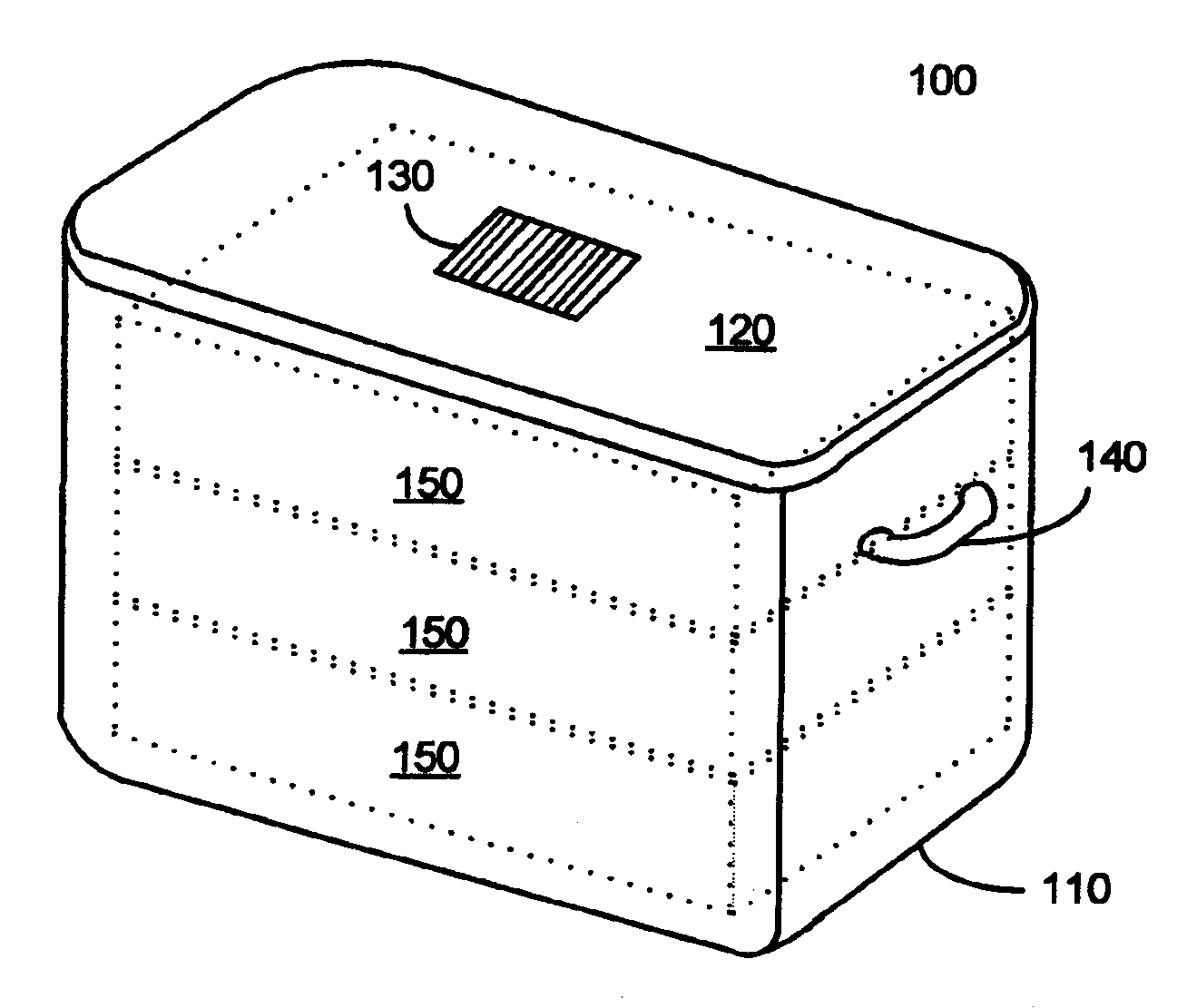
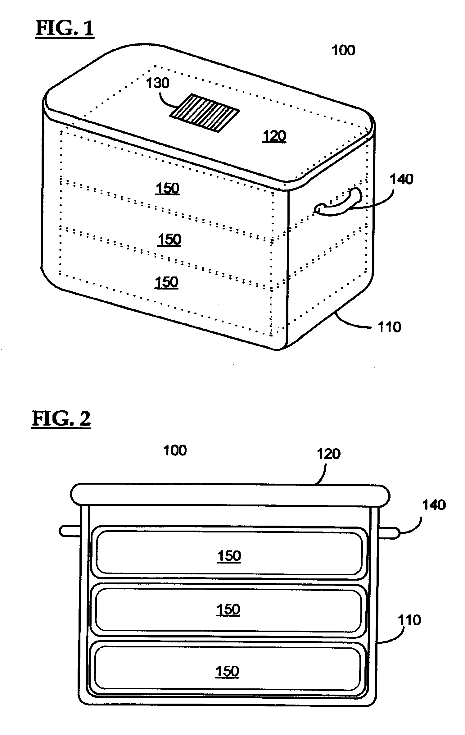
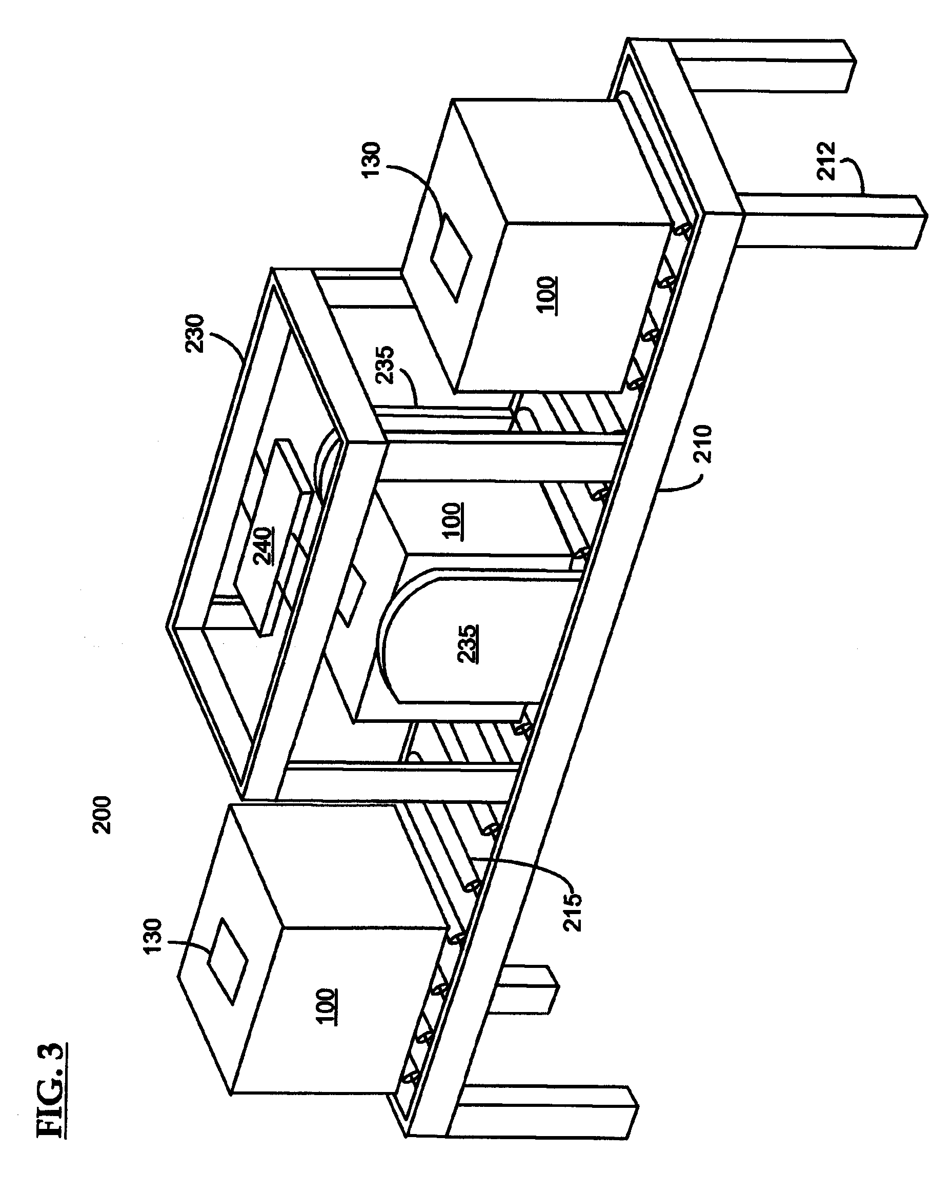
  • Control system for an rfid-based system for assembling and verifying outbound surgical equipment corresponding to a particular surgery
  • Control system for an rfid-based system for assembling and verifying outbound surgical equipment corresponding to a particular surgery
  • Control system for an rfid-based system for assembling and verifying outbound surgical equipment corresponding to a particular surgery

Examples


Embodiment Construction

[0023] The following description is intended to convey a thorough understanding of the invention by providing specific embodiments and details involving systems and methods of processing outbound surgical instrument tray shipping totes and control and / or operating systems for systems for processing outbound surgical instrument tray shipping totes corresponding to a particular surgery. It is understood, however, that the invention is not limited to these specific embodiments and details, which are exemplary only. It further is understood that one possessing ordinary skill in the art, in light of known systems and methods, would appreciate the use of the invention for its intended purposes and benefits in any number of alternative embodiments, depending upon specific design and other needs.

[0024] As used herein, the expressions “RFID tag” and “RFID transponder tag” will refer to any active or passive type of electronic data storage device, read-only or read and write, that is wireles...


PUM


Abstract

A control system for an RFID-based system for assembling and verifying outbound surgical equipment corresponding to a particular surgery. A user enters a identification number of a surgery. The control system queries a database of surgery information and outputs a list of required surgical equipment, such as surgical instrument sets. An operator uses the list to pick instrument sets for loading into a shipping tote. Each set is tagged with an RFID inventory tag that stores identification information for that set such as a set name and ID number. The shipping tote is passed through an RFID reader and identification data read from the tags is compared against the identification data for sets required for that surgery. A status indicator is activated to alert a user as to whether the surgery is complete that is, all expected sets are present, or that exception handling is required. The control system updates a database such as an ERP system to reflect that the surgery including the required sets has shipped—and the sets are inventoried out to the intended recipient.

Description

CROSS REFERENCE TO RELATED APPLICATION(S) [0001] This application is a continuation-in-part of U.S. patent application Ser. No. 10 / 993,487 entitled “Surgical Instrument Tray Shipping Tote Identification System and Methods of Using Same,” filed Nov. 22, 2004, the disclosure of which is hereby incorporated by reference in its entirety.FIELD OF THE INVENTION [0002] The invention generally relates to systems and methods for implementing radio frequency identification techniques, and more particularly to control systems for an RFID-based system for assembling and verifying outbound surgical equipment corresponding to a particular surgery. BACKGROUND OF THE INVENTION [0003] Surgical instrument storage and sterilization systems are known. These systems, sometimes referred to as surgical instrument trays or surgical instrument kits / sets, typically consist of metal or plastic trays that hold a variety of general purpose and / or procedure specific surgical instruments such as forceps, scissors...

Claims


Application Information

Patent Timeline
IPC IPC(8): G08B1/08
CPCG08B13/2462G06Q10/08
Inventor CAMBRE, CHRISTOPHER DAVIDCHUN, CHAD WENDELVARNER, ROBERTSHETTLER, AMYTETHRAKE, STEVEN M.
Owner WARSAW ORTHOPEDIC INC
Learn More