Rotating cylinder multi-program and auto-stereoscopic 3D display and camera

a multi-program, 3d display technology, applied in the direction of instruments, electrical appliances, pictoral communication, etc., can solve the problems of large distance between the first set of optics, the expense of using two monitors concurrently, and the prior art is easily observable, so as to save electric energy

Inactive Publication Date: 2006-05-25
ALDEN RAY M
View PDF16 Cites 76 Cited by
  • Summary
  • Abstract
  • Description
  • Claims
  • Application Information

AI Technical Summary

Benefits of technology

[0018] It is an advantage of the present invention that the same monitor that presents multiple positionally segmented image streams also can provide true positionally segmented auto stereoscopic 3D images as well as stereoscopic images as well as standard 2D images.
[0019] It is an advantage of the present invention that one or more users can experience immersive auto-stereoscopic 3D video images or multiple concurrent video streams from inside a rotating dome, cylinder, conic section, or another shape conducive of being rotated. It is an advantage of the present invention that one or more users can experience auto-stereoscopic 3D video images or multiple concurrent video streams from outside of a rotating dome, cylinder, conic section, or another shape conducive of being rotated.
[0020] It is an advantage of the present invention that a rotating screen is described which rotates around an axis that is either perpendicular to the viewing angle or which is parallel to the viewing axis or is otherwise positioned for optimal viewing.
[0021] IT is an object of the present invention to provide an auto-stereoscopic 3D camera for recording immersive video.
[0022] It is an advantage that both the reflective lenticular screen and the transmissive lenticular reflecting screen are cheap to produce and very reliable.
[0023] Further objects and advantages will become apparent from the enclosed figures and specifications.DRAWING FIGURES

Problems solved by technology

DuMont further requires the expense of using two monitors concurrently.
No known prior art provides a technique to enable multiple viewers to view separate video streams and watch auto stereoscopic 3D programs on a display without a diminution of resolution
Two main disadvantages of this prior art are easily observable when viewing their prototypes.
A first disadvantage is that a large distance on the order of feet is required between the first set of optics and the steering means, and between the steering means and the second set of optics.
This disadvantage results in a display that is far too bulky for consumer markets or for any flat panel display embodiments.
Secondly, looking at the display through large distances between optics creates a tunnel effect that tends to diminish the apparent viewable surface area of the resultant viewing screen.
Increasing resolution using this methodology requires optics to manipulate the image at the sub pixel level or alternately, larger distances between pixel at the chip level, thus the actuation of the DLP chip approach to increasing resolution is not easily upgradeable without substantial cost to a user.

Method used


Image

  • Rotating cylinder multi-program and auto-stereoscopic 3D display and camera
  • Rotating cylinder multi-program and auto-stereoscopic 3D display and camera
  • Rotating cylinder multi-program and auto-stereoscopic 3D display and camera

Examples


second embodiment

[0036]FIG. 8a illustrates a rotating lenticular dome comprising a transmissive steering array with a user on the outside of the dome.

[0037]FIG. 8b illustrates the system of FIG. 8a rotationally advanced at a subsequent time.

third embodiment

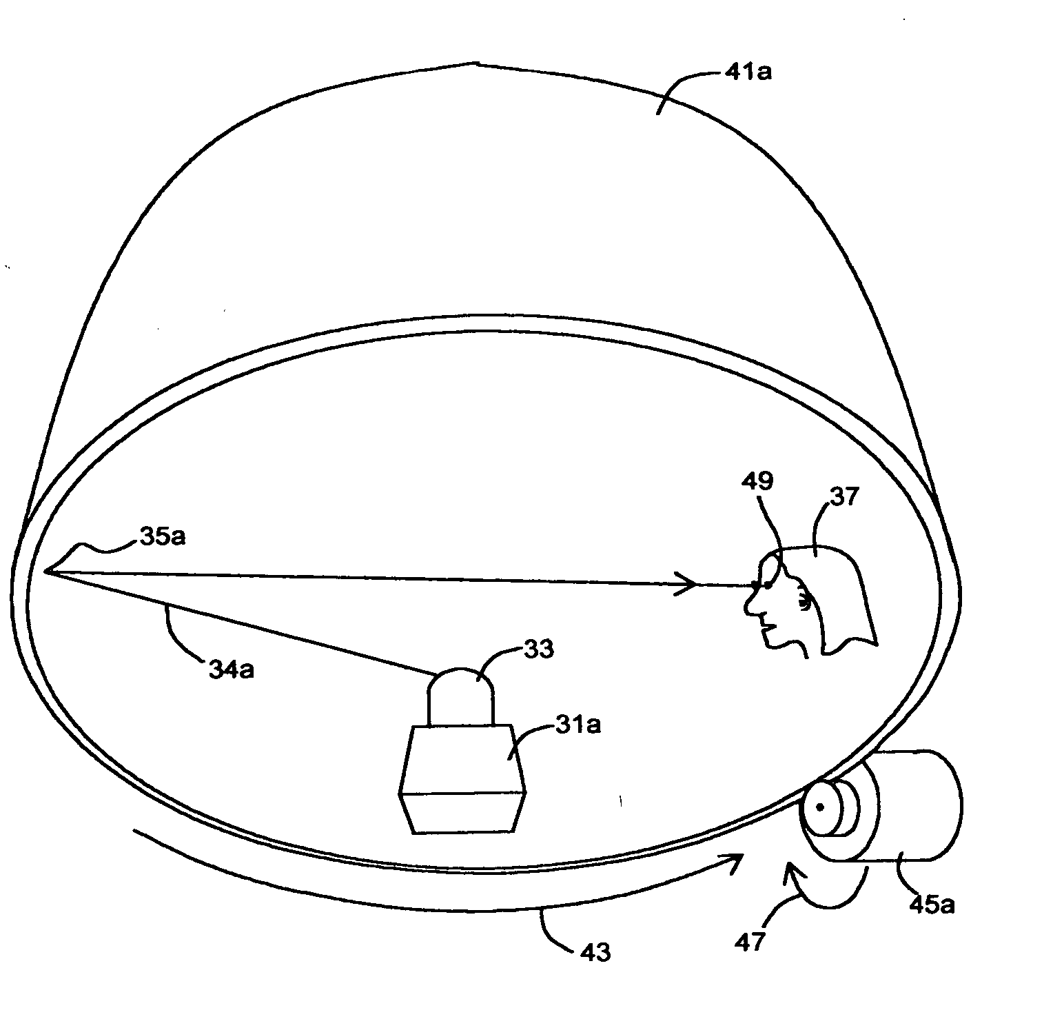
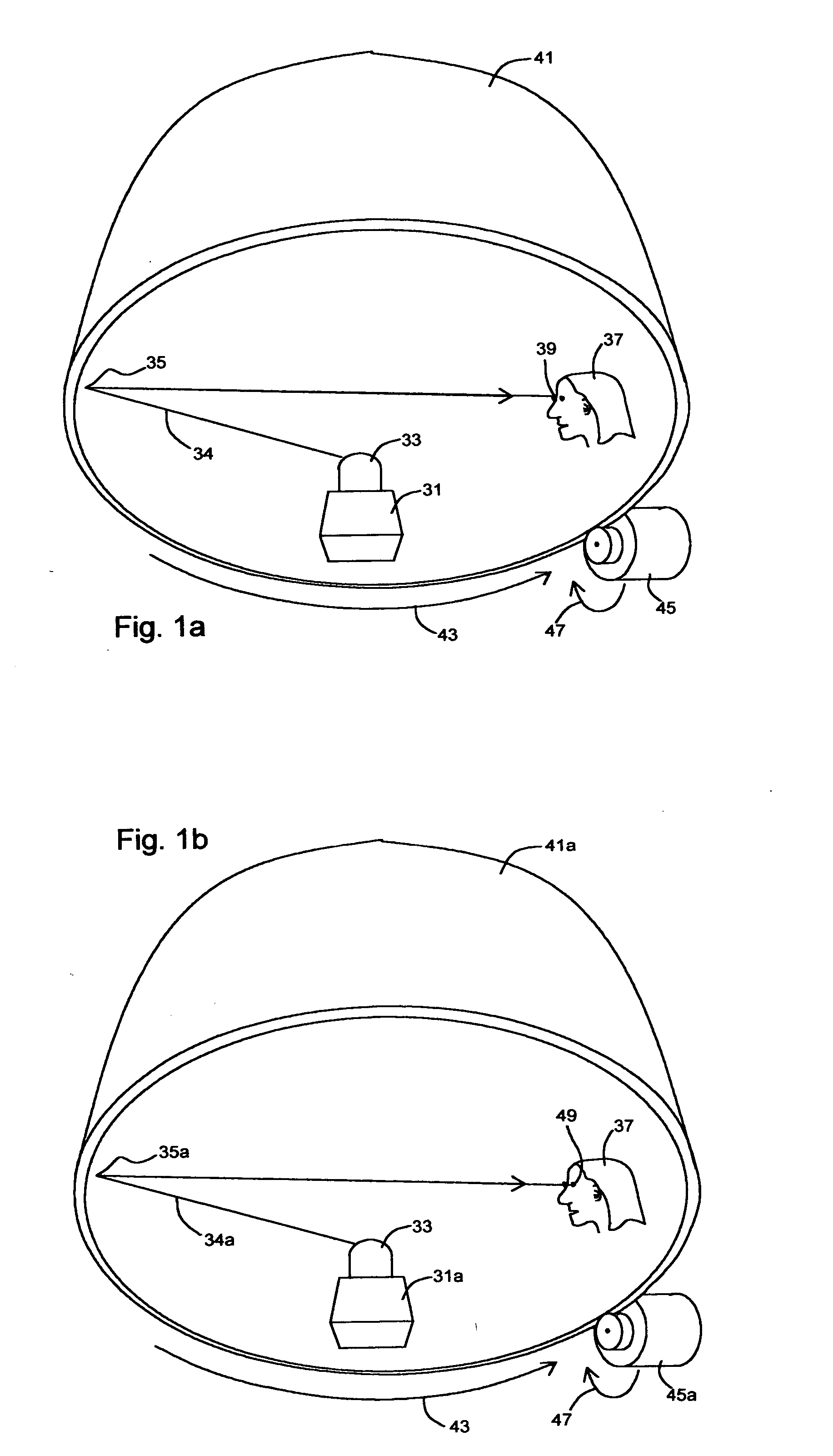
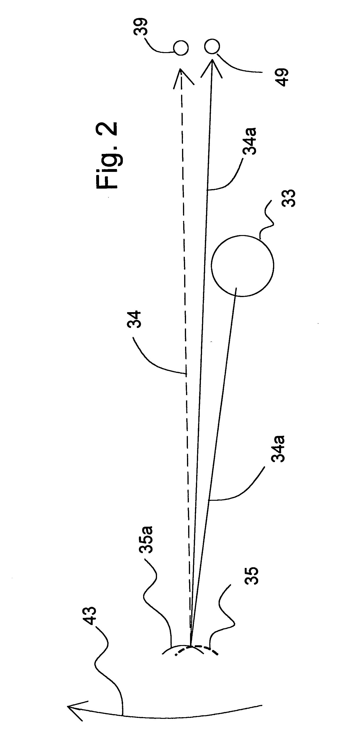
[0038]FIG. 9a illustrates a rotating lenticular dome comprising a transmissive steering array with a user on the inside of the dome.

[0039]FIG. 9b illustrates the system of FIG. 9a rotationally advanced at a subsequent time.

fourth embodiment

[0040]FIG. 10a illustrates a rotating lenticular dome comprising a reflective steering array with a user on the outside of the dome.

[0041]FIG. 10b illustrates the system of FIG. 8a rotationally advanced at a subsequent time.

[0042]FIG. 11 illustrates a cylindrically shaped rotating pixel steering array which can be substituted for the domes described in previous Figures.

[0043]FIG. 12 illustrates a non-diffusing transmissive lenticular in combination with a light filter.

[0044]FIG. 13 illustrates a light diffusing cylinder surface in combination with a light filter.

[0045]FIG. 14 illustrates multiple users interacting with an auto stereoscopic 3D and multiple program display.

[0046]FIG. 15a illustrates a rotating transmissive lenticular array steering light from a light emitting array and viewable from inside the lenticular cylinder.

[0047]FIG. 15b illustrates the rotating transmissive lenticular array steering of FIG. 15a in operation.

[0048]FIG. 15c illustrates a rotating transmis...


PUM


Abstract

The invention described herein represents a significant improvement for the users of displays. In a first reflective immersive embodiment, a rotating encompassing projection screen with integral horizontal and vertical reflective lenticulars completely surrounds users to enable multiple users to concurrently watch completely different programs including auto-stereoscopic 3D programs in an immersive venue format which is highly reliable and cheap to produce. In a second transmissive immersive embodiment, a rotating encompassing projection screen with integral horizontal and vertical transmissive lenticulars completely surrounds users to enable multiple users to concurrently watch completely different programs including auto-stereoscopic 3D programs in an immersive venue format which is highly reliable and cheap to produce. In a third embodiment, a rotating projection screen with integral horizontal and vertical reflective lenticulars enables multiple users to concurrently watch completely different programs including auto-stereoscopic 3D programs in a front projection format which is highly reliable and cheap to produce. In a fourth embodiment, a rotating projection screen with integral horizontal and vertical transmissive lenticulars enables multiple users to concurrently watch completely different programs including auto-stereoscopic 3D programs in a rear projection format which is highly reliable and cheap to produce. Also in recording embodiments, a camera replaces the projector in each respective embodiment to enable recording of auto-stereoscopic 3D scenes.

Description

CROSS-REFERENCE TO RELATED APPLICATIONS [0001] This application is a continuation in part of the following patent applications by the present applicant; U.S. application Ser. No. 10 / 994,556 filed Nov. 22, 2004, U.S. application Ser. No. 11 / 050,619 filed Feb. 2, 2005, and U.S. application Ser. No. 11 / 095,403 filed Mar. 31, 2005.BACKGROUND [0002] 1. Field of Invention [0003] Modern video display devices incorporate many technologies and methods for providing high quality video to users. Nearly every household in the United States has one or more video displays in the form of a television or a computer monitor. These devices generally use technologies such as Cathode Ray Tubes (CRT) tubes, FEDs, Liquid Crystal Displays (LCD), OLEDs, Plasma, Lasers, LCoS, Digital Micromirror Devices (DMD), front projection, rear projection, or direct view in one way or another. Large monitors offer the advantage of enabling many users to see the video monitor simultaneously as in a living room televisio...

Claims


Application Information

Patent Timeline
Patent Type & Authority Applications(United States)
IPC IPC(8): G09G5/00
CPCH04N13/0228H04N13/0282H04N13/0296H04N13/0404H04N13/0422H04N13/0447H04N13/0497H04N13/305H04N13/282H04N13/324H04N13/229H04N13/296H04N13/398H04N13/351
Inventor ALDEN, RAY M.
Owner ALDEN RAY M
Why Eureka
Try Eureka