Wireless access control station and wireless access control method

Inactive Publication Date: 2006-05-25
CANON KK
View PDF9 Cites 7 Cited by
  • Summary
  • Abstract
  • Description
  • Claims
  • Application Information

AI Technical Summary

Benefits of technology

[0013] The present invention has been made in consideration of the above problems, and has as its object to change between the distributed coordination function and the point coordination function regardless of the connection direction between the wireless access control sta

Problems solved by technology

However, a parameter implementation method is not particularly defined.
This method cannot be applied to upload connection from the wireless station to the wireless access control station, thus posing a problem.
Therefore, this scheme cannot

Method used


Image

  • Wireless access control station and wireless access control method
  • Wireless access control station and wireless access control method
  • Wireless access control station and wireless access control method

Examples


first embodiment

[0035] According to the first embodiment of the present invention, an image display apparatus which is compatible with a QoS function under examination in “IEEE802.11e / D8.0 February 2004” and has a wireless LAN access point function will be exemplified. The wireless LAN according to the first embodiment is obtained by adding the QoS function under examination in the IEEE802.11e draft of “IEEE802.11e / D8.0 February 2004” to an IEEE802.11g 2.4-GHz Band wireless LAN scheme. Contrary to this QoS wireless station, the conventional wireless LAN station incompatible to “IEEE802.11e / D8.0 February 2004” is called a non-QoS wireless station.

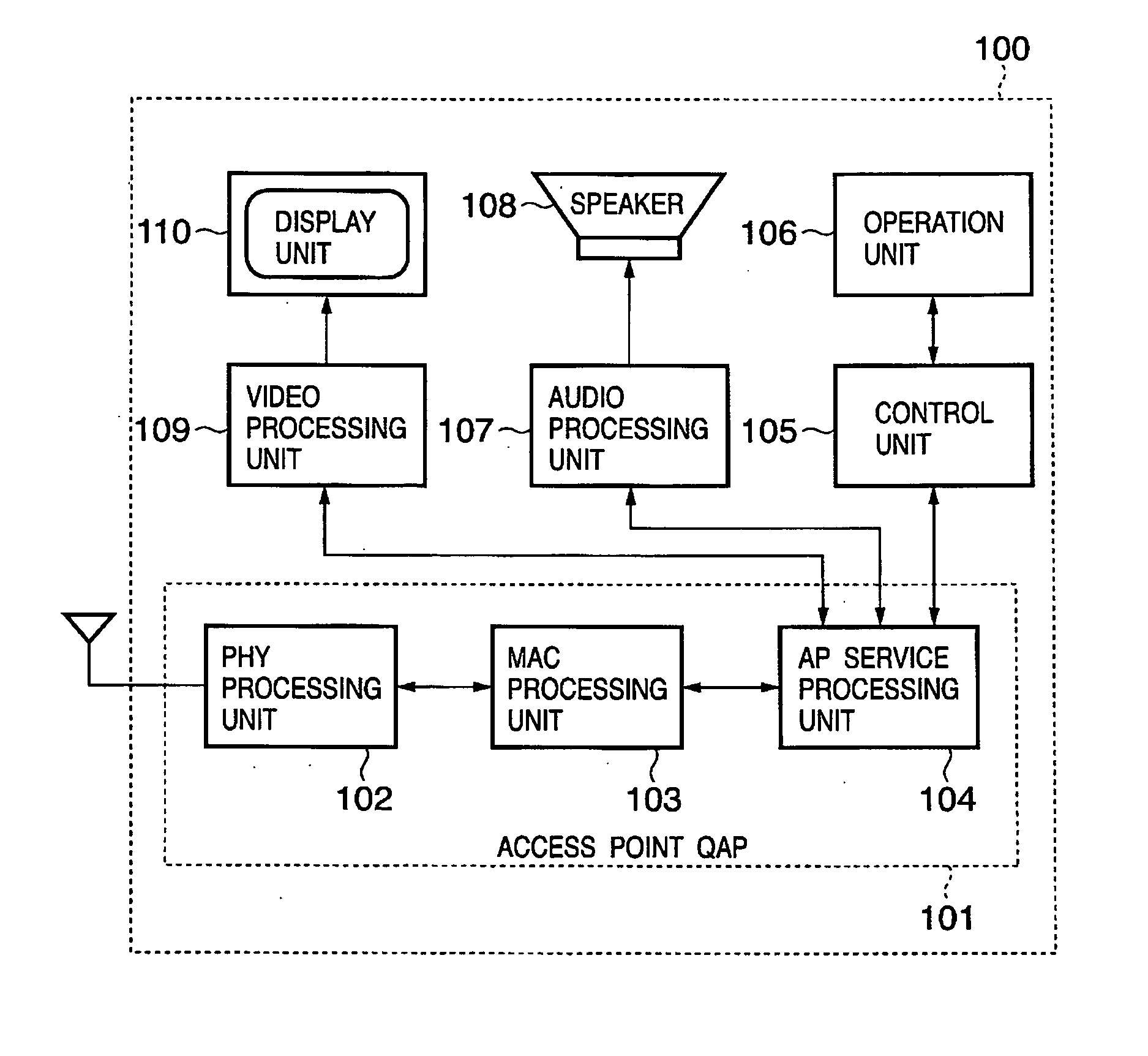
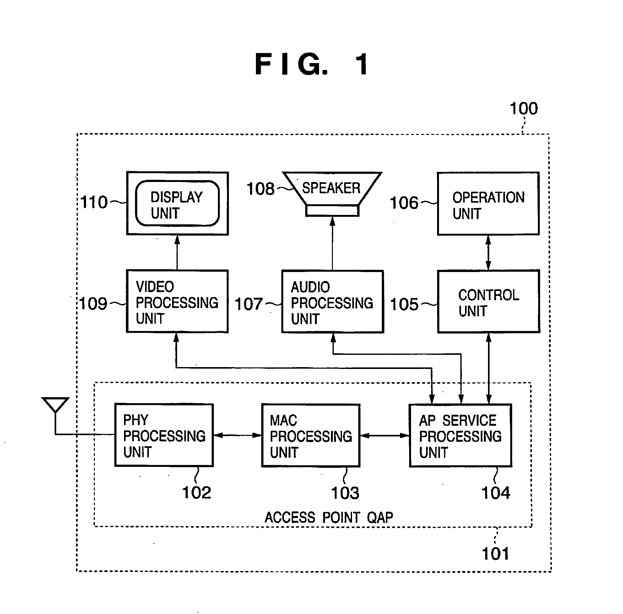
[0036]FIG. 1 is a block diagram showing an arrangement of an image display apparatus 100 having an access point function according to the first embodiment.

[0037] In FIG. 1, reference numeral 101 denotes a QoS-compatible access point (QAP) (to be referred to as an access point 101 hereinafter) according to the first embodiment. Reference numeral 102 denote...

second embodiment

[0137] In the first embodiment, the third threshold value γ is a fixed value. However, the third threshold value γ may be a variable in accordance with a factor such as the number of connected stations. In the second embodiment, the third threshold value γ is a variable.

[0138]FIG. 12 is a flowchart showing an example of the second embodiment, and an update procedure of first, second, and third threshold values α, β, and γ when the third threshold value γ becomes a variable. In the second embodiment, the update flow of the first, second, and third threshold values α, β, and γ is also updated for each beacon cycle as the process shown in FIG. 8.

[0139] In FIG. 12, step S21 is the same as step S1, and steps S31 to S36 are the same as steps S2 to S7, so a description thereof will be omitted. When the first and second threshold values α and β are updated in steps S35 and S36 after this process starts or the beacon cycle ends, a collision count parameter “m” is initialized to “0” in step...

third embodiment

[0154] In the first embodiment, the priority in the information table is determined from the mode, AC, and Mean Data Rate. However, the priority may be determined by using a parameter such as a Minimum Data Rate obtained from a TSPEC, or a Peak Data Rate. The priority may also be determined in accordance with remaining information in the TSPEC.

[0155] Furthermore, in a first wireless station apparatus 201 or second wireless station apparatus 202 having a plurality of wireless channels, prior to connection of a video channel and audio data transmission channel, an aperiodical data transmission channel may be connected. The application of the access point 101 may receive station control information similar to a TSPEC information element from the application of the second wireless station apparatus 202 via the aperiodical data transmission channel.

[0156] In the first embodiment, the AP manager 301 evaluates the connection count of the wireless channels in the flow shown in FIG. 9, in ...


PUM


Abstract

Even in a wireless station only having a distributed coordination function, a fair connection chance can be provided. A wireless access control station comprising a determination unit which determines a wireless connection count of a predetermined access category, and a change unit which changes, in accordance with determination obtained by said determination unit, wireless connection of a wireless communication apparatus satisfying a predetermined condition from a wireless connection of distributed coordination function to a wireless connection of point coordination function, or from the wireless connection of point coordination function to the wireless connection of distributed coordination function.

Description

FIELD OF THE INVENTION [0001] The present invention relates to a wireless access control station and wireless access control method and, for example, to a technique suitably used to optimally switch between point coordination and distributed coordination in a wireless LAN apparatus. BACKGROUND OF THE INVENTION [0002] In a wireless LAN standard IEEE802.11, as an access control mechanism for sharing a single wireless channel among a plurality of wireless stations, two functions are defined, i.e., a DCF (Distributed Coordination Function) and a PCF (Point Coordination Function), using a MAC (Medium Access Control) layer function. [0003] In accordance with the DCF (Distributed Coordination Function), each wireless station independently performs collision avoidance of a wireless channel using a CSMA / CA (Career Sense Multiple Access with Collision Avoidance) function, ensures the wireless channel on so-called “first-come, first-served” basis, and communicates with another wireless station...

Claims


Application Information

Patent Timeline
IPC IPC(8): H04Q7/00H04Q7/28H04L12/28H04B7/26H04W4/00H04W74/00H04W74/02H04W74/04H04W74/08H04W84/12
CPCH04L47/10H04L47/14H04L47/2441H04L47/25H04L47/29H04W74/02H04W28/0284H04W8/04
Inventor IMAEDA, EIJI
Owner CANON KK
Why Eureka
Try Eureka