Package for electric apparatus

a technology for electric appliances and packaging, applied in the direction of packaging goods, transportation and packaging, damagable goods, etc., can solve the problems of high cost and complicated operation of packaging members, and achieve the effect of efficient housing

Inactive Publication Date: 2006-06-01
ORION ELECTRIC CO LTD
View PDF0 Cites 29 Cited by
  • Summary
  • Abstract
  • Description
  • Claims
  • Application Information

AI Technical Summary

Benefits of technology

[0007] In view of these problems, it is an object of the present invention to provide a package for an electric apparatus which allows a power supply cord to be efficiently housed when an electric apparatus is packed and which enables the power supply cord to be appropriately held in a packaging box.

Problems solved by technology

The patent references deal with problems such as the complicatedness of an operation of housing a power supply cord in a dedicated packaging member (for example, a box) and higher costs resulting from an increase in the number of packaging members.
However, when the power supply cord connected to the electric apparatus main body is housed in the packaging box in which the electric apparatus is packed or in the cushioning material, that operation may be complicated (since the power supply cord is connected to the electric apparatus main body and there is a fixed relationship between the electric apparatus main body and the packaging box or cushioning material, the positional relationship between the power supply cord and the packaging box or cushioning material is limited, thus complicating operations such as fitting of the power cord into the packaging box or cushioning material)

Method used


Image

  • Package for electric apparatus
  • Package for electric apparatus
  • Package for electric apparatus

Examples


embodiment 1

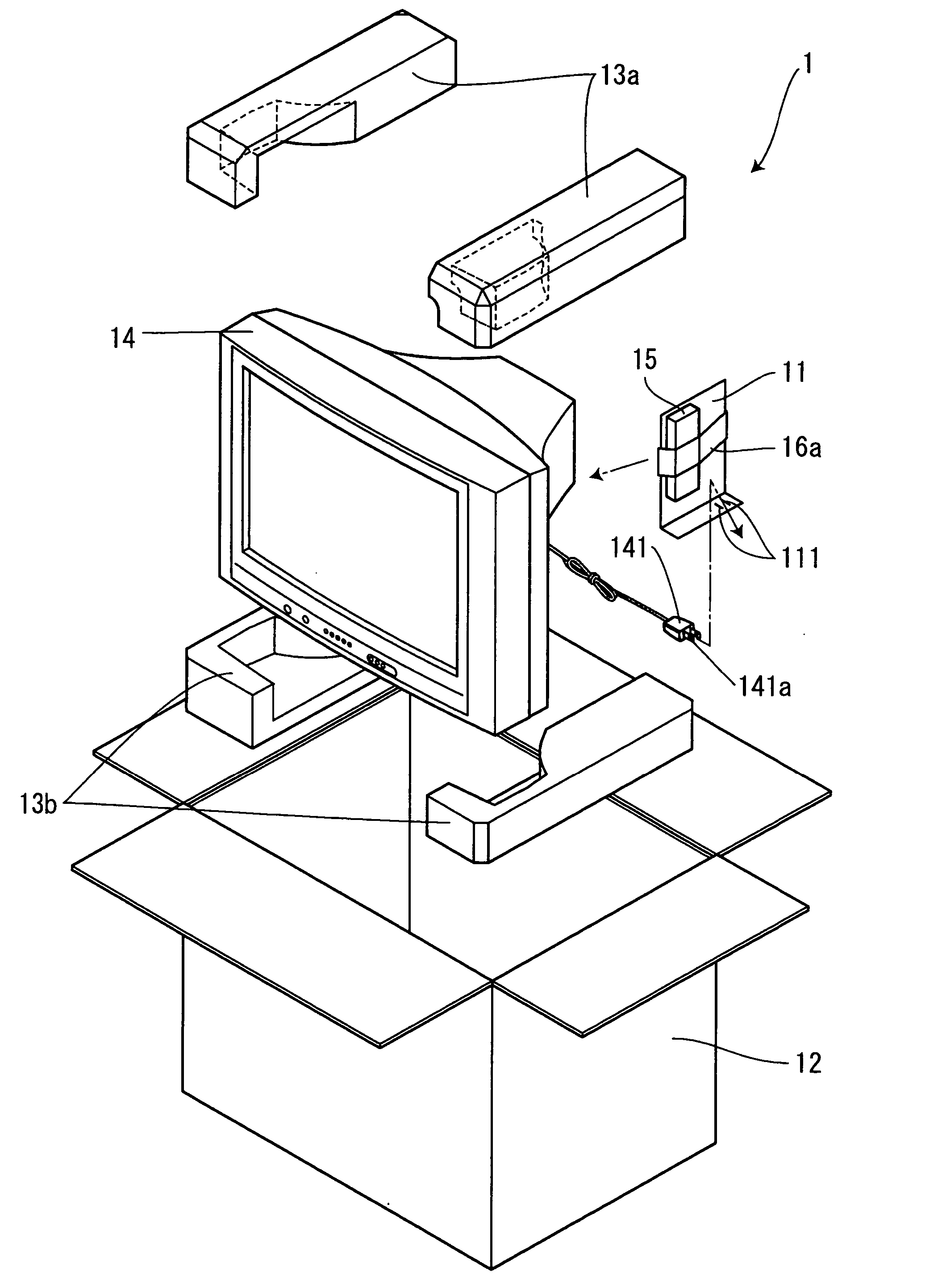
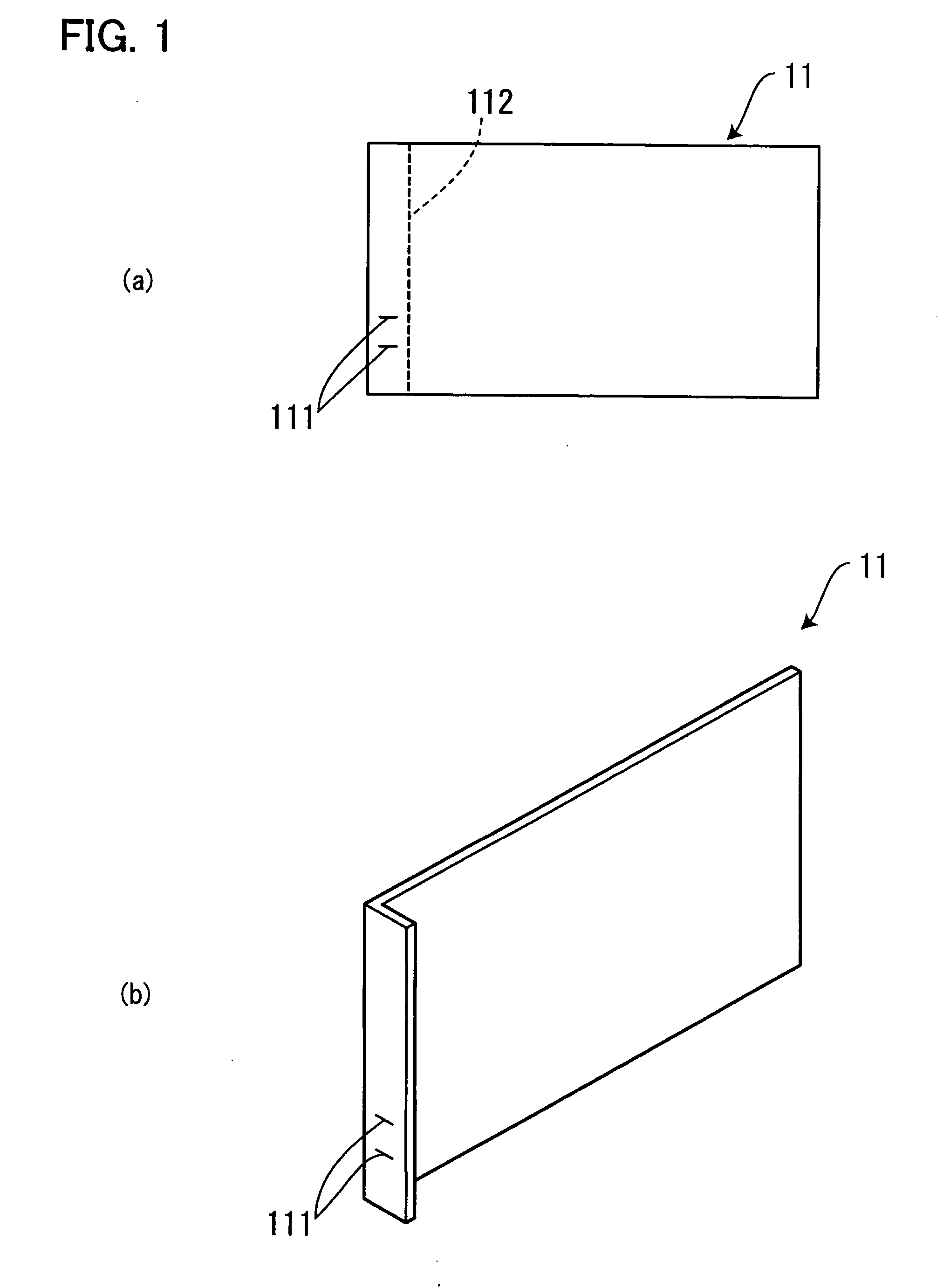
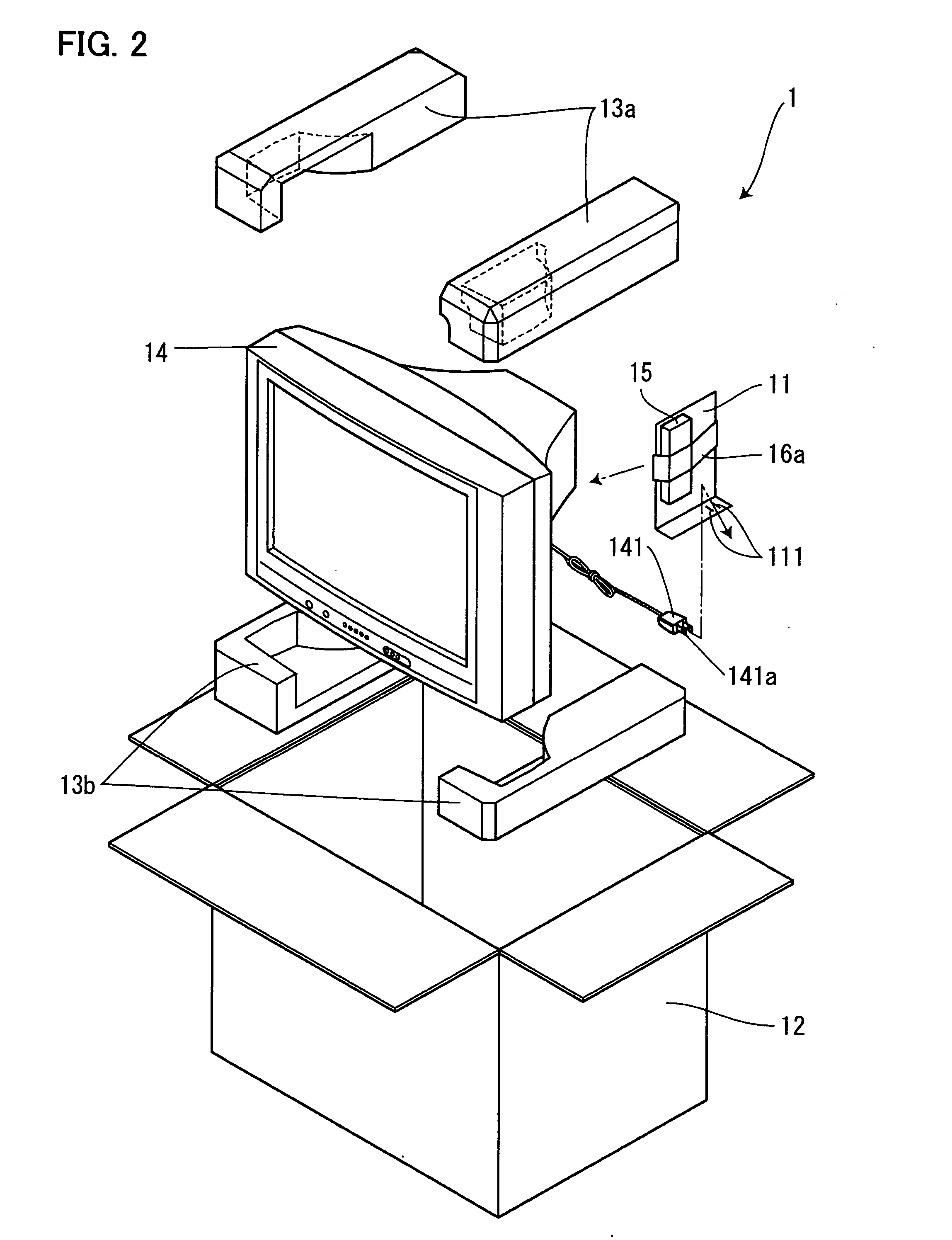
[0043]FIG. 1 is a diagram schematically showing a power supply plug holding member in accordance with the present embodiment. FIG. 2 is a perspective view showing that a package for an electric apparatus in accordance with the present embodiment is opened. FIG. 3 is a partly exploded plan view of the package.

[0044] As shown in FIG. 1, a power supply plug holding member 11 in accordance with the present embodiment is generally L-shaped (FIG. 1b) by forming cut-in portions 111 through which a plug terminal 141a of a power supply plug 141 of an electric apparatus (television) 14 is inserted, in a corrugated fiberboard that is a foldable packaging material and folding the corrugated fiberboard at a dashed line 112 in FIG. 1a (FIG. 1b). The cut-in portions 111 are formed during a pressing operation of cutting the corrugated fiberboard into an external shape (rectangle) shown in FIG. 1a. Accordingly, only the required operation is folding of the corrugated fiberboard into a general L sha...

embodiment 2

[0047]FIG. 5 is a diagram schematically showing a power supply plug holding member in accordance with the present embodiment. FIG. 6 is a perspective view showing that a package for an electric apparatus in accordance with the present embodiment is opened. FIG. 8 is a partly exploded plan view of the package.

[0048] As shown in FIG. 5, a power supply plug holding member 50 in accordance with the present embodiment is generally U-shaped by forming cut-in portions 51, 52, and 53 through which a plug terminal of a power supply plug of an electric apparatus (recording and reproducing apparatus) 61 is inserted, in a substantially rectangular corrugated fiberboard (foldable packaging material) having a latitudinal (the latitudinal direction is shown by y in FIG. 5(a)) length that is substantially the same as the inside height (shown by x in FIG. 8(c)) of a packaging box 62, and then folding the corrugated fiberboard, in the same direction, at two dashed lines 55 shown in FIG. 5(a). A plur...

embodiment 3

[0052]FIG. 11 is a diagram schematically showing a power supply plug holding member in accordance with the present embodiment. FIG. 12 is a partly exploded plan view of a package for an electric apparatus in accordance with the present embodiment. The same reference numerals as those in Embodiment 2 are used to denote components of the present embodiment which are similar to those of Embodiment 2.

[0053] As shown in FIG. 11, a power supply plug holding member 1100 in accordance with the present embodiment is generally U shaped as shown in FIGS. 11(b) and 11(c) by forming cut-in portions 1101 and 1102 through which the plug terminal 611a of the power supply plug 611 (or power supply plug 93) of the recording and reproducing apparatus 61, which is an electric apparatus, is inserted, in a generally rectangular corrugated fiberboard (foldable packaging material) having a latitudinal (the latitudinal direction is shown by z in FIG. 11(a)) length that is substantially the same as the insi...


PUM

PropertyMeasurementUnit
pressureaaaaaaaaaa
lengthaaaaaaaaaa
dimensionsaaaaaaaaaa

Abstract

To provide a package for an electric apparatus which allows a power cord to be efficiently housed when an electric apparatus is packed and which enables the power supply cord to be appropriately held in a packaging box. A power supply plug holding member 50 is formed by creating a cut-in portion 52 through which a power supply plug 611 is inserted, in a foldable packaging material such as a corrugated fiberboard and then folding the packaging material into a general U shape. The power supply plug 611 of an electric apparatus 61 is locked in the cut-in portion 52 in the power supply plug holding member 50, which is then housed between a packaging box 62 and the electric apparatus 61.

Description

[0001] The present application is based on and claims priority of Japanese patent application No. 2004-346433 filed on Nov. 30, 2004, the entire contents of which are hereby incorporated by reference. BACKGROUND OF THE INVENTION [0002] 1. Field of the Invention [0003] The present invention relates to a package for an electric apparatus, and in particular, to a package made taking into account housing of a power supply cord of an electric apparatus. [0004] 2. Description of the Related Art [0005] Packaging boxes such as corrugated fiberboard boxes have hitherto been widely used to transport articles without damage. To pack an electric apparatus or the like which is not resistant to an impact, for example, a cushioning material such as styrene foam is filled into the box. Further, the electric apparatus may be provided with an accessory such as a power supply cord extending from the electric apparatus main body or a remote control device. Accordingly, packing of these members must be ...

Claims


Application Information

Patent Timeline
Patent Type & Authority Applications(United States)
IPC IPC(8): B65D71/00B65D85/00B65D81/02
CPCB65D81/107
Inventor SHIMIZU, DAISUKEMUKOUGAWA, HIDENOBUHORIE, TAKAYUKIMITOMORI, YASUOYOSHIDA, TSUYOSHI
Owner ORION ELECTRIC CO LTD
Why Eureka
Try Eureka