Hanger beam construction

a technology of beams and hangers, which is applied in the field of beam construction of hangers, can solve the problems of reducing the strength of the beam, reducing the use of materials, and affecting the performance of the beam, so as to reduce the use of materials, and increase the strength and stability

Inactive Publication Date: 2006-06-01
RANDY HANGERS L L C
View PDF5 Cites 2 Cited by
  • Summary
  • Abstract
  • Description
  • Claims
  • Application Information

AI Technical Summary

Benefits of technology

[0011] A garment hanger comprises a hook member and pinch grips as well as a body member comprising a molded beam with an “S”- or “Z”-shaped cross section. The “S”- and “Z”-shaped cross sections provide greater strength and stability to the beam and body member to reduce warping and reduce the use of material. The cross sections generally comprise a curved shape with a top, bottom, and middle section. The middle section may comprise at least two bends or an incline connecting the top and bottom sections. The garment hanger may have a separately attached hook or be of one-piece, molded construction. The beam design may also be used on an insert that is attached to the hook of another hanger.

Problems solved by technology

Unfortunately, the hanger body or beam portion is subject to a substantial amount of wear and tear due to the heaviness or weight of the clothing material and frequent use.
Particularly, a substantial amount of warping in molded hangers occurs in the beam.
The designs currently used in the art do not provide a strong structure and therefore do not sufficiently address this problem.

Method used


Image

  • Hanger beam construction
  • Hanger beam construction
  • Hanger beam construction

Examples


Embodiment Construction

[0020] While this invention is illustrated and described in a preferred embodiment, the device may be produced in many different configurations, forms and materials. There is depicted in the drawings, and will herein be described in detail, a preferred embodiment of the invention, with the understanding that the present disclosure is to be considered as an exemplification of the principles of the invention and the associated functional specifications for its construction and is not intended to limit the invention to the embodiment illustrated.

[0021]FIGS. 1-6 illustrate “S”- and “Z”-shaped designs that may be in a forward-facing or reversed direction without changing or having an affect on the scope of the present invention. Those skilled in the art will envision many other possible variations within the scope of the present invention.

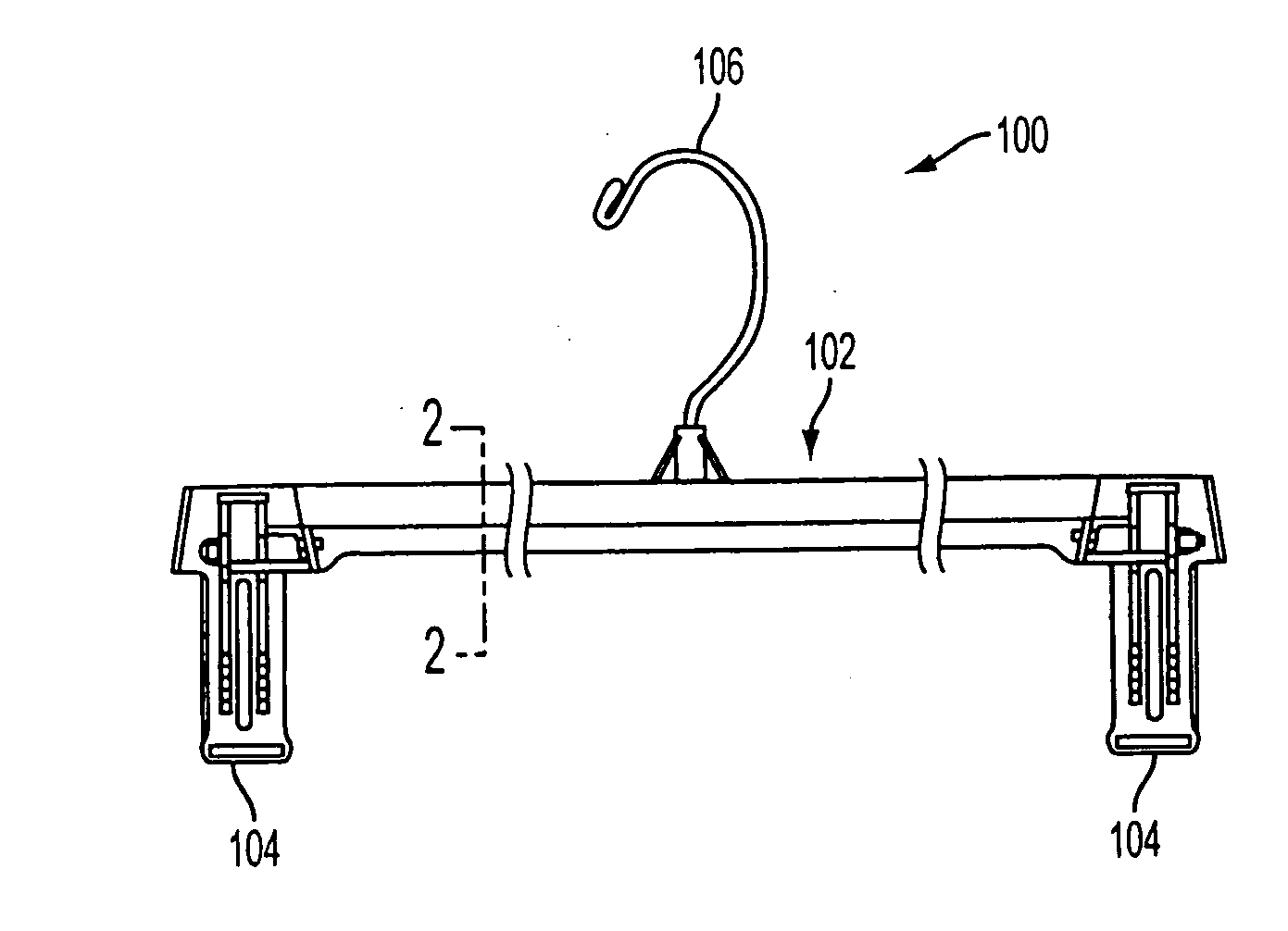
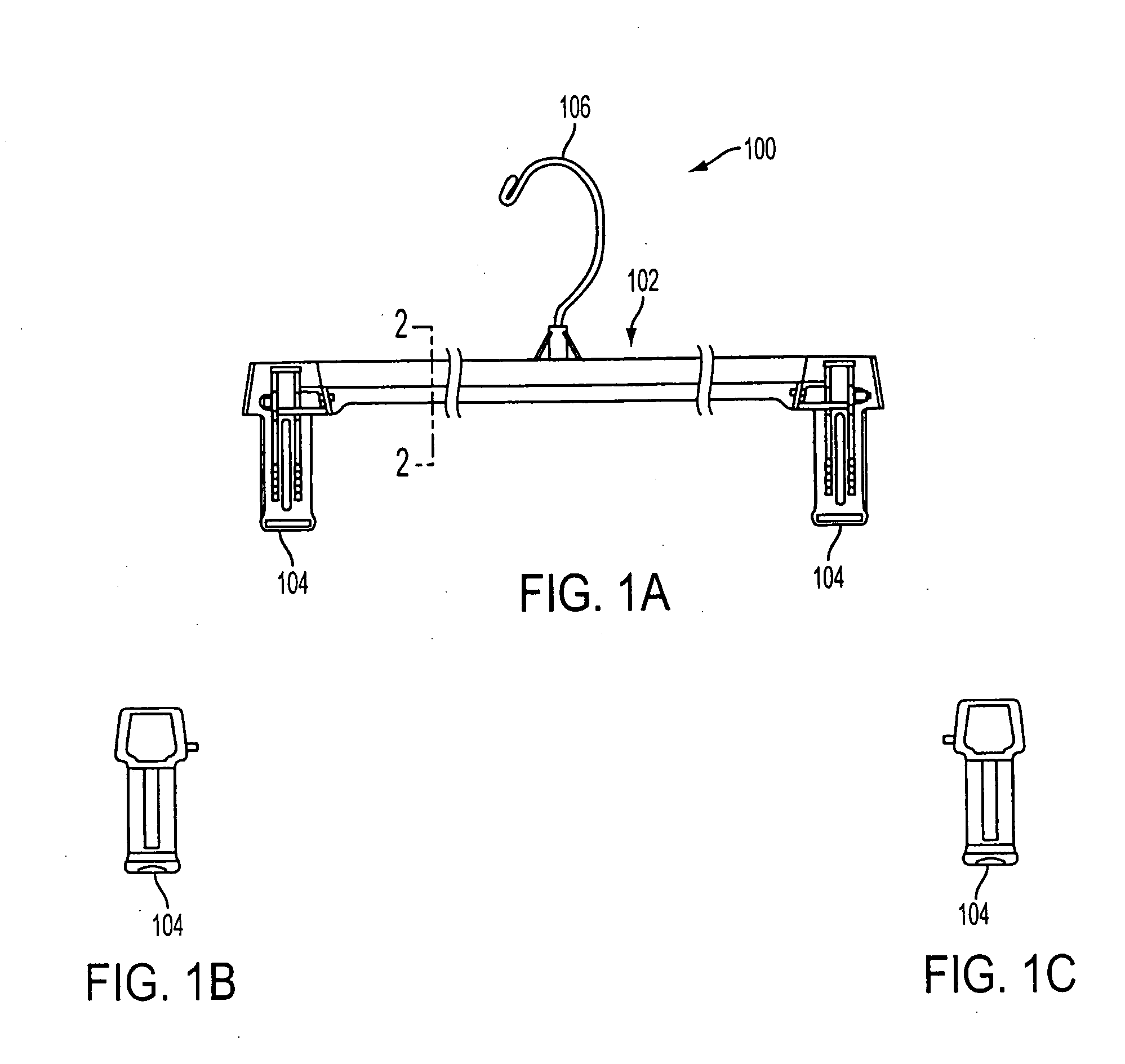
[0022]FIGS. 1a, 1b and 1c illustrate one embodiment of a hanger of the present invention. Therein, FIG. 1a illustrates a profile view; FIGS. 1b and 1...


PUM


Abstract

A garment hanger comprising pinch grip clips has a unique molded beam design for added strength and stability. The cross-section of the hanger beam comprises an “S”-shaped design extending along the beam between the pinch grip clips. The “S”-shaped construction reduces warping in the beam body that may be caused by heavy clothing material or frequent use. Alternatively, a “Z”-shaped design may also be used.

Description

BACKGROUND OF THE INVENTION [0001] 1. Field of Invention [0002] The present invention relates generally to the field of beam construction for a hanger. More specifically, the present invention is related to a beam construction having increased strength and stability with reduced warping and material requirements. [0003] 2. Discussion of Prior Art [0004] Pinch grip garment hangers are typically used to hold clothing and garments such as pants or skirts or undergarments. Therein, a garment hanger requires strength and stability to hold clothing of all weights and sizes. Garment hangers may be molded in one complete design or comprised of several parts, for example the hook or clips, attached to a molded body. [0005] The strength and stability of the hanger comes from its beam design. Unfortunately, the hanger body or beam portion is subject to a substantial amount of wear and tear due to the heaviness or weight of the clothing material and frequent use. Particularly, a substantial amo...

Claims


Application Information

Patent Timeline
Patent Type & Authority Applications(United States)
IPC IPC(8): A41D27/22
CPCA47G25/28A47G25/485
Inventor RITZMANN, ELLEN STEINPLUCHINO, JOSEPH
Owner RANDY HANGERS L L C
Why Eureka
Try Eureka