Axial air-gap electronic motor

a technology of electronic motors which is applied in the direction of rotating magnets, magnetic circuit rotating parts, synchronous machines with stationary armatures, etc., can solve the problems of increasing the weight of the rotor itself, increasing the manufacturing cost, and axial air gap electronic motors that are not suitable for use, so as to reduce the noise and vibration at the time of operation.

Active Publication Date: 2006-06-01
FUJITSU GENERAL LTD
View PDF22 Cites 41 Cited by
  • Summary
  • Abstract
  • Description
  • Claims
  • Application Information

AI Technical Summary

Benefits of technology

[0026] The rotor magnet is preferably formed so that the thickness thereof is small at both ends in the rotation direction for each magnetic pole, and the thickness thereof in the central portion is larger than that at both ends in the circumferential direct...

Problems solved by technology

However, the conventional axial air-gap electronic motor has problems as described below.
Also, in the method described in Patent Document 2, the magnet and attachment member used exclusively for position detection are required, so that not only the manufacturing cost increases accordingly but also the weight of the rotor itself increases because of the additional installation of the detecting magnet, thereby increasing electric power consumption.
In the hole forming process, the posi...

Method used


Image

  • Axial air-gap electronic motor
  • Axial air-gap electronic motor
  • Axial air-gap electronic motor

Examples


Embodiment Construction

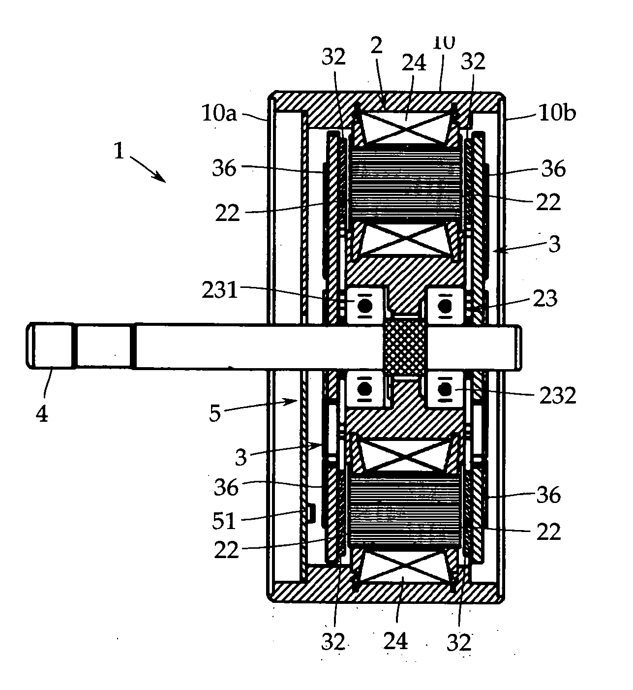
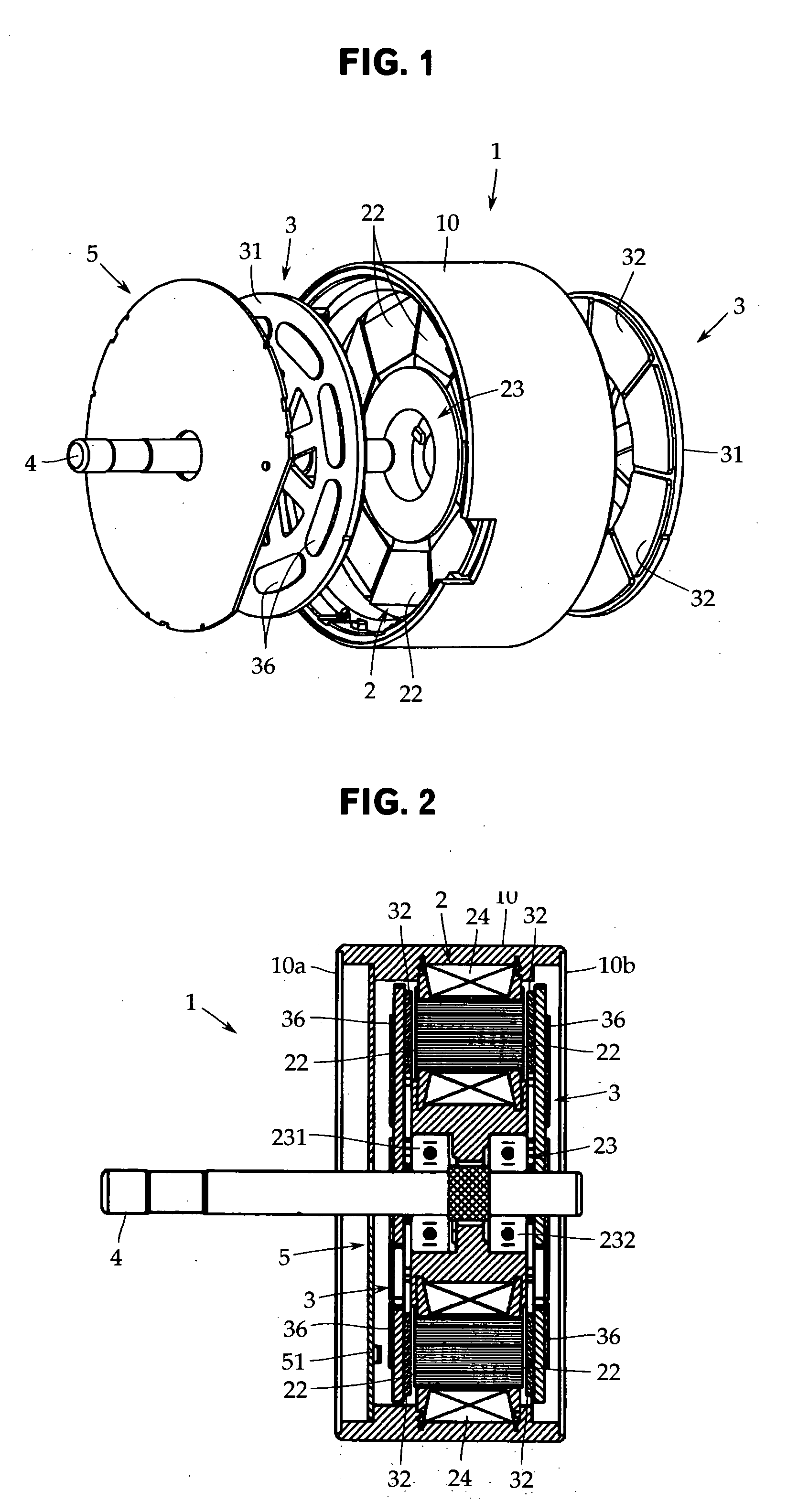
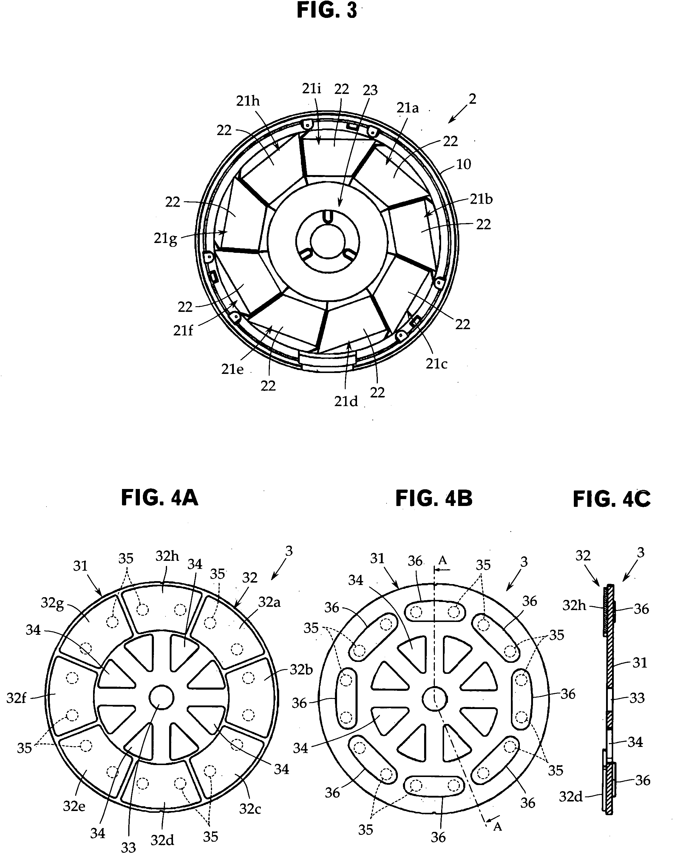
[0040] Embodiments of the present invention will now be described with reference to the accompanying drawings. The present invention is not limited to these embodiments. FIG. 1 is an exploded perspective view of an axial air-gap electronic motor in accordance with a first embodiment of the present invention, and FIG. 2 is a central longitudinal sectional view of the first embodiment. FIG. 3 is a front view of a stator, and FIGS. 4A to 4C are a front view, a back view, and an A-A sectional view, respectively, of a rotor of the first embodiment.

[0041] This axial air-gap electronic motor 1 includes a stator 2 formed into a disc-shape and a pair of rotors 3 arranged opposedly on both side surfaces of the stator 2 with a predetermined gap being provided therebetween. The rotors 3 are fixed coaxially on a rotor output shaft 4 for developing a rotation driving force.

[0042] The stator 2 and the rotors 3 are housed in a cylindrical housing 10. In this example, at both ends of the housing 1...


PUM


Abstract

There is provided, at a low cost, an axial air-gap electronic motor capable of preventing a magnet from coming off and carrying out position detection more surely. In an axial air-gap electronic motor in which the teeth surface of a stator and the magnet surface of a rotor are arranged opposedly with a predetermined gap being provided therebetween along the axis line direction of the output shaft of the rotor, the rotor has a rotor back yoke arranged coaxially with the stator and a rotor magnet installed to the rotor back yoke so as to face to the teeth surface of the stator, and the rotor magnet is provided with an anchor magnet which is integral with the rotor magnet and is arranged on the back surface side of the rotor back yoke.
The anchor magnet 36 integral with the rotor magnet 32 via a through hole 35 is provided on the back surface side of the rotor back yoke 31 of the rotor 3, thereby fixing the rotor magnet 32, and further position detection is carried out by the anchor magnet 36.

Description

TECHNICAL FIELD [0001] The present invention relates to an axial air-gap electronic motor in which a rotor and a stator are opposedly arranged along the axial direction of a rotor output shaft. More particularly, it relates to an axial air-gap electronic motor in which a rotor magnet can be fixed surely to a rotor back yoke. BACKGROUND ART [0002] For example, as shown in Patent Document 1 (Japanese Patent Application Publication No. H03-212141), an axial air-gap electronic motor is a motor in which a rotor is arranged opposedly on one side surface or both side surfaces of a stator with a predetermined gap being provided therebetween, and is characterized in that the thickness thereof in the rotating shaft direction can be decreased, namely, the motor can be made flat as compared with a radial air-gap electronic motor such as an inner rotor type. [0003] Usually, the rotor consists of a rotor back yoke formed by a disc-shaped body and a rotor magnet attached integrally to the surface ...

Claims


Application Information

Patent Timeline
IPC IPC(8): H02K21/12H02K1/22
CPCH02K1/2793H02K21/24H02K1/2798H02K11/215H02K29/08H02K15/03H02K1/182H02K2213/03H02K2201/03
Inventor TANNO, TOSHIAKIKOJIMA, TOMONORI
Owner FUJITSU GENERAL LTD
Why Eureka
Try Eureka