

Magnetic field generating apparatus and method for magnetic resonance imaging
- Summary
- Abstract
- Description
- Claims
- Application Information
AI Technical Summary
Problems solved by technology
Method used
Image

Examples
Embodiment Construction
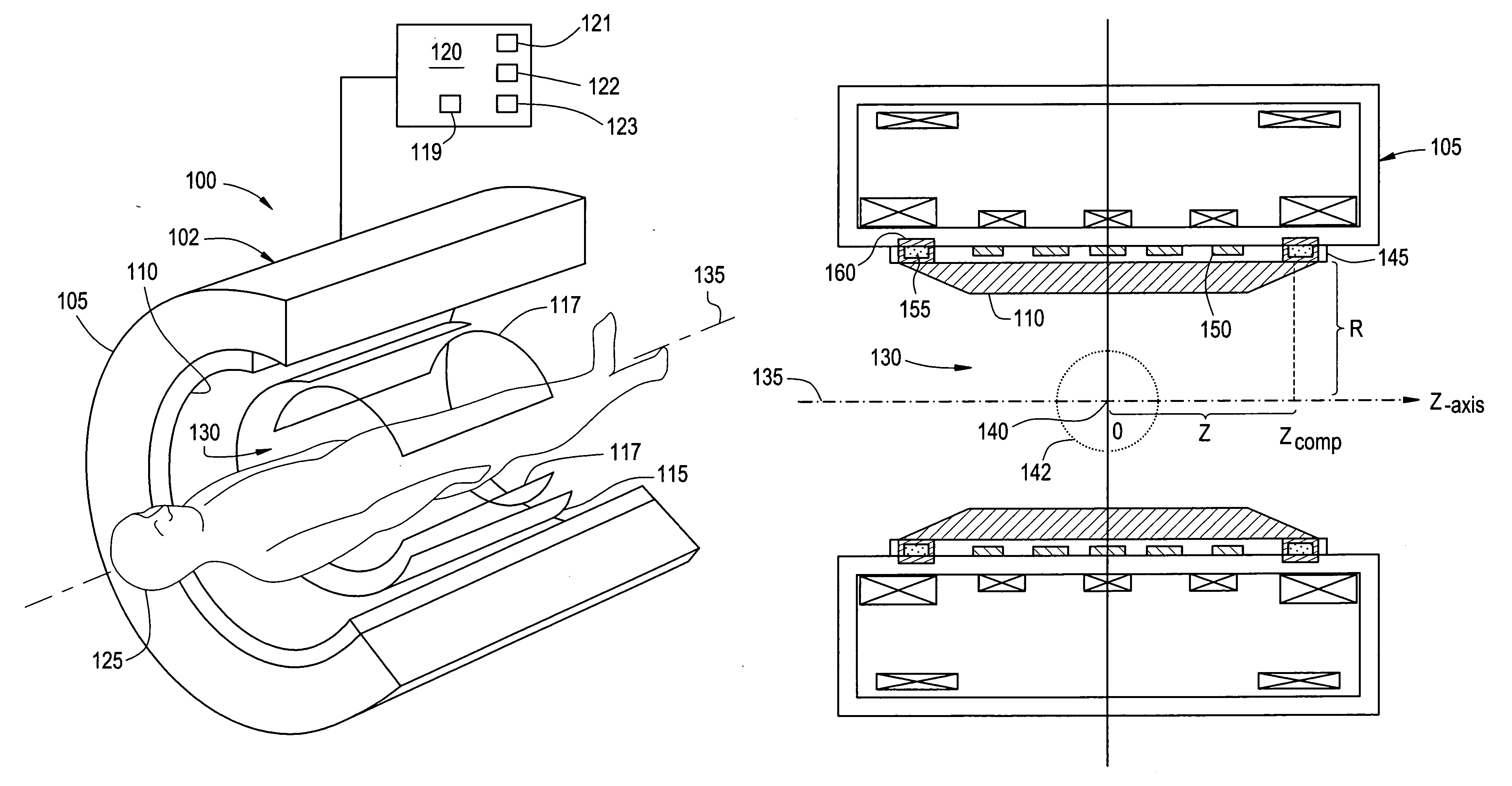
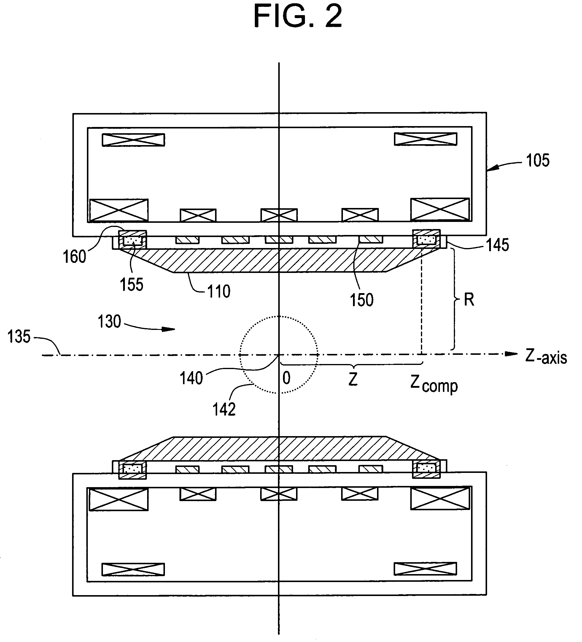
[0013] An embodiment of the invention provides a magnetic field generating apparatus for use in magnetic resonance imaging (MRI) having two sets of magnetic field adjusting shim elements. A first set of shim elements are configured to compensate for the inhomogeneities resulting from the main field generator, and a second set of shim elements are configured to compensate for the inhomogeneities resulting from a temperature change in the first set of shim elements. While embodiments described herein depict two sets of shim elements, it will be appreciated that the disclosed invention is not so limited and may also be applicable to multiple sets of shim elements, particularly with respect to the second set of shim elements.
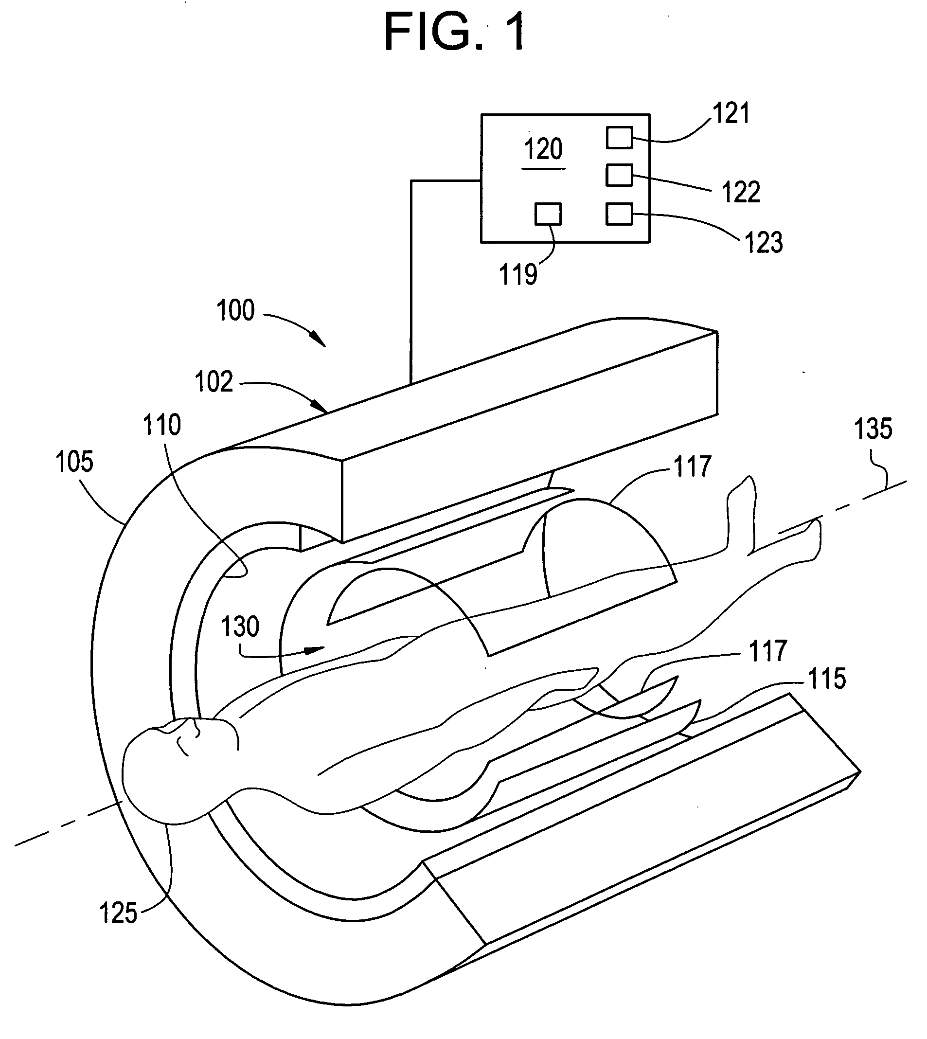
[0014]FIG. 1 depicts an exemplary embodiment of an MRI system 100 having a magnetic field generating apparatus 102 and a control system 120 for the control and operation thereof. An exemplary apparatus 102, shown having a portion cutaway to show structure within ap...
PUM
 Abstract
Description
Claims
Application Information