Method and apparatus for replicating the position of intra-osseous implants and abutments relative to analogs thereof

a technology of intra-osseous implants and analogs, applied in dental implants, dental surgery, medical science, etc., can solve the problems of inability to accurately reproduce the position of intra-osseous implants and abutments, the nature of the fit of the post in the abutment is unpredictable, and the degree of retention is unpredictable, so as to increase the retention resistance of the cylindrical post, reduce the build-up of hydraulic pressure, and reduce the effect of abutment analogs

Inactive Publication Date: 2007-05-08
DEBBIE
View PDF4 Cites 56 Cited by
  • Summary
  • Abstract
  • Description
  • Claims
  • Application Information

AI Technical Summary

Benefits of technology

[0007]According to another embodiment, an implant analog is formed with a shelf in the bore of the implant analog located at a distance from the mouth of the bore, i.e., the top surface of the implant analog, essentially equal to the distance between the bottom end face of the tapered post of a permanent abutment and the longitudinal axial position on the tapered post at the top face surface of the permanent implant with the permanent abutment in the locked position upon receiving clinical tapping insertion force. The shelf prevents a tapered permanent abutment post from over-seating in an implant analog, which is particularly important when the implant analog is composed of plastic material. According to a feature of the invention, the cylindrical bore of the implant analog can be provided with one or more flats to increase the retention resistance of a cylindrical post, with or without a taper, received therein as well as to pro

Problems solved by technology

However, titanium has a major limitation relating to the phenomenon of memory.
It is possible for the diameter of the slotted post to either widen or narrow over time making the nature

Method used


Image

  • Method and apparatus for replicating the position of intra-osseous implants and abutments relative to analogs thereof
  • Method and apparatus for replicating the position of intra-osseous implants and abutments relative to analogs thereof
  • Method and apparatus for replicating the position of intra-osseous implants and abutments relative to analogs thereof

Examples


Embodiment Construction

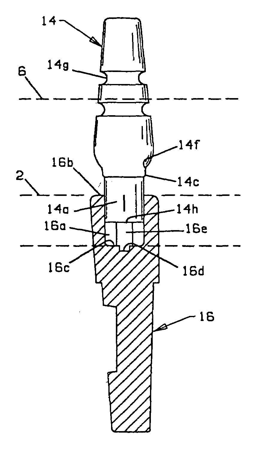
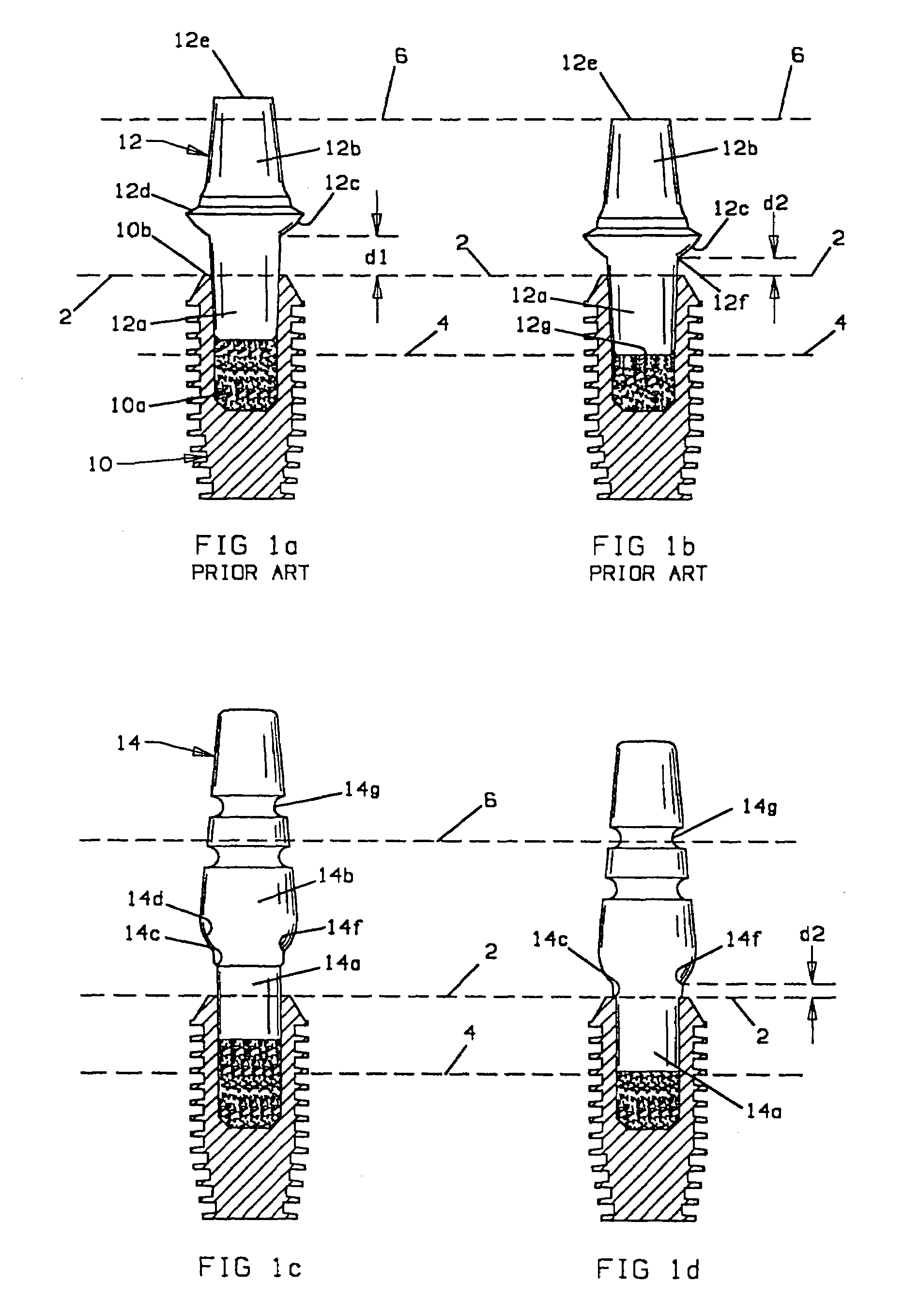
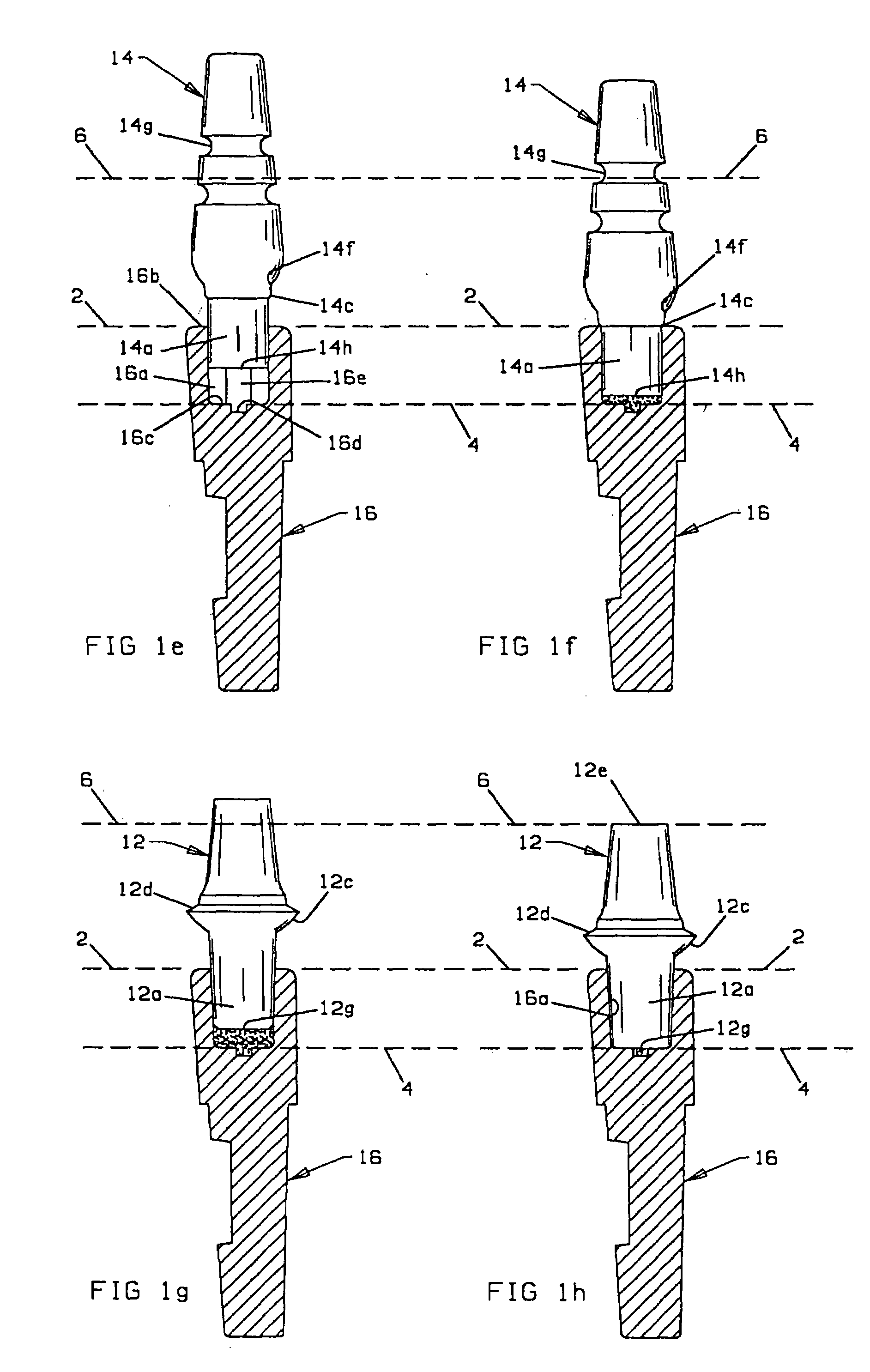
[0015]With reference to FIGS. 1a, 1b, a conventional implant 10 is shown having a well or bore 10a formed with a female locking taper as disclosed in detail in U.S. Pat. No. 4,738,623 referenced above. Dashed line 2 extends through the top end surface 10b of the implant shown in FIGS. 1a–1d and the top end surface 16b of the implant analogs shown in FIGS. 1e–1h to be discussed. Dashed lines 4 and 6 show the same reference distances from dashed line 2 in the respective figures. The post 12a of an abutment 12, also provided with a male locking taper, is received in bore 10a at a first apical position relative to the top end surface 10b of the implant when a first lower pressure level is used to place the implant, as by finger pressure. Dashed line 2 aligned with the top end surface 10b denotes the axial position of post 12a in the first, partially seated position at a distance d1 measured along the longitudinal axis of post 12a and bore 10a from a reference point of the abutment, e.g....


PUM


Abstract

The position of intra-osseous implants and abutments to analogs is enabled and enhanced by using the longitudinal axial locked position of a post (12a) of an implant (12) having a locking taper in a bore (10a) of an implant (10) having a generally matching locking taper as a reference to determine the position of a stop surface (14c) on impression posts, abutment analog posts and the like received in the bore of an implant and implant analog. In another embodiment the bore (16) of an implant analog (16) is provided with a shelf (16c) located at a position determined by the axial distance of the locked position of the abutment post to prevent over-seating. Controlled retentive resistance and stability of a post is provided by using flats formed in the bore of an implant analog and by forming rings on a post receivable in the bore of an implant or implant analog. One such ring (18c) is formed with an outer periphery sized and configured to allow bending of the outer peripheral portion in a direction opposite to the direction of insertion in a bore to provide greater retentive resistance than insertion resistance.

Description

RELATED APPLICATIONS[0001]Benefit is claimed of provisional application No. 60 / 274,498 filed Mar. 9, 2001.FIELD OF THE INVENTION[0002]This invention relates generally to medical and dental implant devices and more particularly to a method for transferring the relative position of an intra-osseous implant relative to a laboratory replicated position, as in a dental abutment, and for determining the appropriate height of a dental abutment received in an implant for an aesthetic submucosal prosthetic margin placement.BACKGROUND OF THE INVENTION[0003]Implant systems comprising an implant having a tapered bore adapted to receive therein an abutment post or the like formed with a matching taper for retention of the post in the implant are known. See for example U.S. Pat. No. 4,738,623, assigned to the assignee of the present invention, the disclosure of which is incorporated herein by this reference. It is also known to provide such posts, which are intended to be used as impression posts...

Claims


Application Information

Patent Timeline
IPC IPC(8): A61C8/00
CPCA61C8/0001A61C8/00
Inventor MORGAN, VINCENT J.
Owner DEBBIE
Why Eureka
Try Eureka