Sealing arrangement for a rolling-contact bearing

a sealing arrangement and bearing technology, applied in mechanical equipment, gearing, hoisting equipment, etc., can solve the problems of ineffective sealing arrangement for vehicles operated off-road operation, unsatisfactory lids in order to provide effective protection, etc., to improve the effectiveness of two-stage sealing arrangement, easy maintenance of sealing arrangement, and cost reduction

Inactive Publication Date: 2005-02-15
SCHAEFFLER TECH AG & CO KG
View PDF24 Cites 55 Cited by
  • Summary
  • Abstract
  • Description
  • Claims
  • Application Information

AI Technical Summary

Benefits of technology

According to another feature of the present invention, an elastic sealing lip may be disposed in outer surrounding relationship to the sealing disk and supported by an end surface of the outer bearing ring. The sealing lips of the first sealing element and the sealing disk are thus supported by different bearing rings thereby further improving the effectiveness of the two-stage sealing arrangement on either side of the rolling elements. The elastic sealing lip may be vulcanized at the outer circumference of the disk element. Of course, other types of fixation are conceivable as well such as, e.g., gluing, of form-fitting connection in which the sealing lip encompasses the outer contour of the disk element by a continuous groove.
The sealing gap, which has a circular ring shaped configuration for receiving the sealing material, is open radially outwards, whereby the first sealing element, which is directly received in the rolling-contact bearing, is supported via the sealing lip upon the inner bearing ring. The sealing material thus effectively provides a pre-sealing action for the sealing lip which is in sliding contact with the inner bearing ring. As a result, ingress of contaminants as well as liquids of any kind is prevented into the rolli

Problems solved by technology

However, this seal arrangement is ineffective for vehicles operated off-road operation and situations, when the vehicle is driven through water or subject to significant ingress of dirt into the installation space intended for the internal combustion engine.
Still, under more ex

Method used


Image

  • Sealing arrangement for a rolling-contact bearing
  • Sealing arrangement for a rolling-contact bearing
  • Sealing arrangement for a rolling-contact bearing

Examples


second embodiment

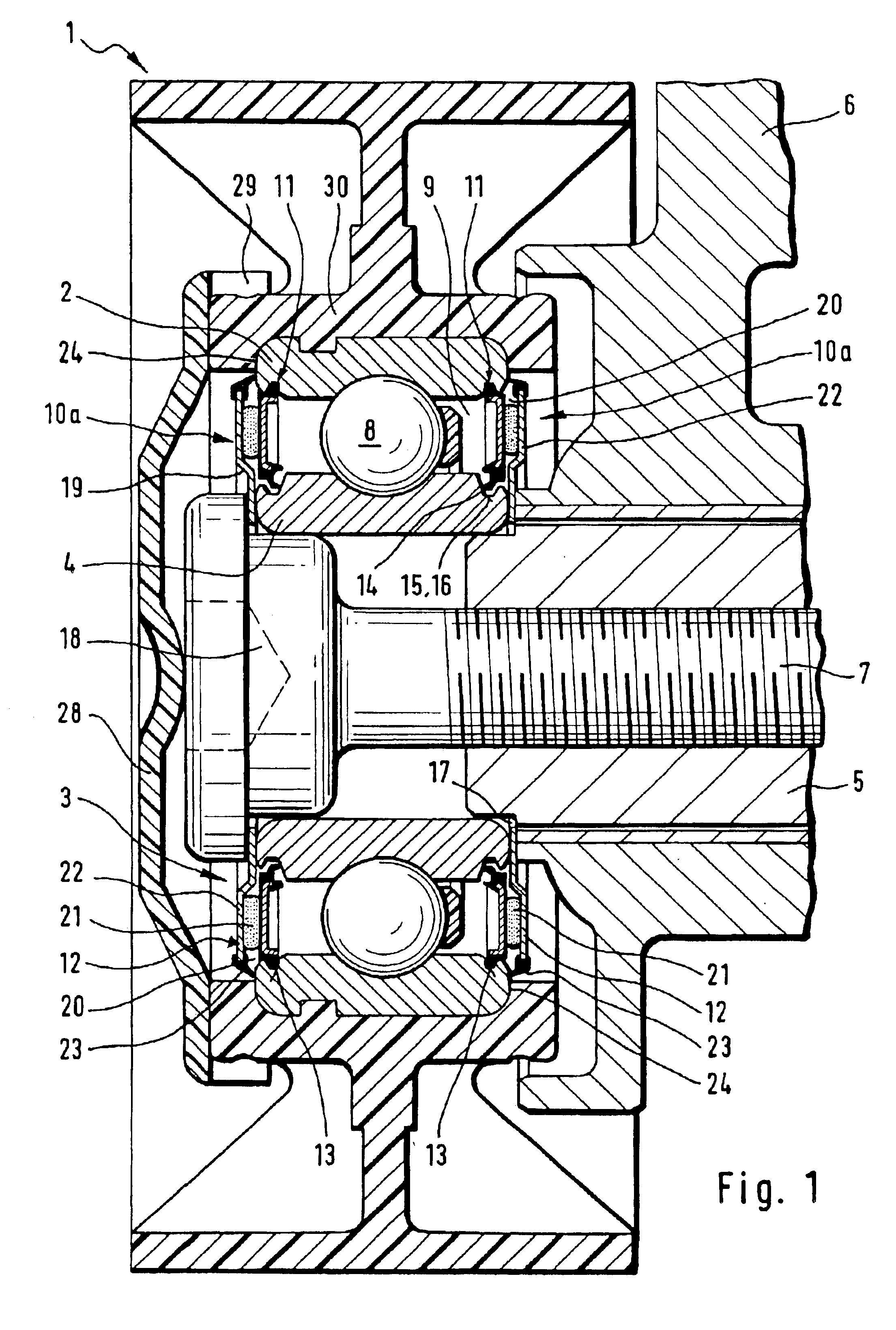
Turning now to FIG. 2, there is shown a sectional view of a tension roller 1 supported by a rolling-contact bearing 3 and having incorporated therein the two-stage sealing arrangement 10a on one side and a sealing arrangement according to the present invention, generally designated by reference numeral 10b on the other side of the rolling-contact bearing 3. Parts corresponding with those in FIG. 1 are denoted by identical reference numerals and not explained again. In this embodiment, the rolling-contact bearing 3 is centered on a carrier ring, generally designated by reference numeral 25 and connected to a housing 26, whereby the inner bearing ring 4 is restrained on a cylindrical portion 25a of the carrier ring 25. The cylindrical portion 25a terminates in a wrap-around radial collar 27 which extends to the contour of the outer bearing ring 2. In the area of the annular gap 9, the collar 27 extends at an axial distance to the sealing element 11, thereby defining the sealing gap 20...

third embodiment

FIG. 3 shows a sectional view of a tension roller 1 supported by a rolling-contact bearing 3 and having incorporated therein the two-stage sealing arrangement 10a on one side and a sealing arrangement according to the present invention, generally designated by reference numeral 10c on the other side of the rolling-contact bearing 3. The description below will center on the differences between the embodiments and in particular on the configuration of the sealing arrangement 10c. In the embodiment of FIG. 3, the sealing gap 20 is defined in axial direction by the sealing element 11 and a radial shoulder 31 which is connected to a cylindrical housing pin 32, with the inner bearing ring 4 being centered on the housing pin 32. Disposed at least partially in the sealing gap 20 is a sealing material, e.g. the grease portion 21.

Turning now to FIG. 4, there is shown a detailed sectional view, on an enlarged scale, of the sealing arrangement 10a to more clearly show the configuration of the s...


PUM


Abstract

A two-stage sealing arrangement for sealing an annular gap between an outer bearing ring and an inner bearing ring of a rolling-contact bearing, includes a first sealing element securely fixed to the outer bearing ring and having at least one sealing lip supported against the inner bearing ring. A second sealing element is disposed at an axial distance to the first sealing element, thereby defining a circular ring shaped sealing gap in a radial direction for accommodating, at least partially, a sealing material.

Description

BACKGROUND OF THE INVENTIONThe present invention relates to a sealing arrangement for a rolling-contact bearing, in particular groove ball bearing.German patent publication DE 41 33 777 describes a rolling-contact bearing with an inner bearing ring, an outer bearing ring, and rolling elements disposed between the inner and outer bearing rings. The rolling-contact bearing is provided to support a tension roller of a belt drive, with a seal disposed on one side of the rolling elements and another seal disposed on the other side of the rolling elements. The seals are secured to the outer bearing ring and seal an annular gap radially bounded by the bearing rings, whereby each seal has a sealing lip for support against the outer surface area of the inner bearing ring. While the arrangement of these seals may in some instances be sufficient to inhibit ingress of contaminants into the rolling-contact bearing or escape of lubricant from the rolling-contact bearing, when, for example, instal...

Claims


Application Information

Patent Timeline
IPC IPC(8): F16C33/78F16C33/76F16C13/00F16H7/08F16H55/36F16J15/18
CPCF16C13/006F16C33/7853F16C33/7859F16C33/723F16H7/20F16C19/06F16C2361/63F16H2007/0865
Inventor SCHMIDT, WERNER
Owner SCHAEFFLER TECH AG & CO KG
Why Eureka
Try Eureka