Phased array planar antenna and a method thereof

Active Publication Date: 2006-06-01
ELTA SYST LTD
View PDF17 Cites 48 Cited by
  • Summary
  • Abstract
  • Description
  • Claims
  • Application Information

AI Technical Summary

Benefits of technology

[0021] According to another embodiment, the third, elevation subsystem being configured to provide a controllably changeable angular orientation between the plane defined by the active subsystem and a plane defined by the azi

Problems solved by technology

However, polarization tracking typically requires a considerable antenna size, f

Method used


Image

  • Phased array planar antenna and a method thereof
  • Phased array planar antenna and a method thereof
  • Phased array planar antenna and a method thereof

Examples


Example

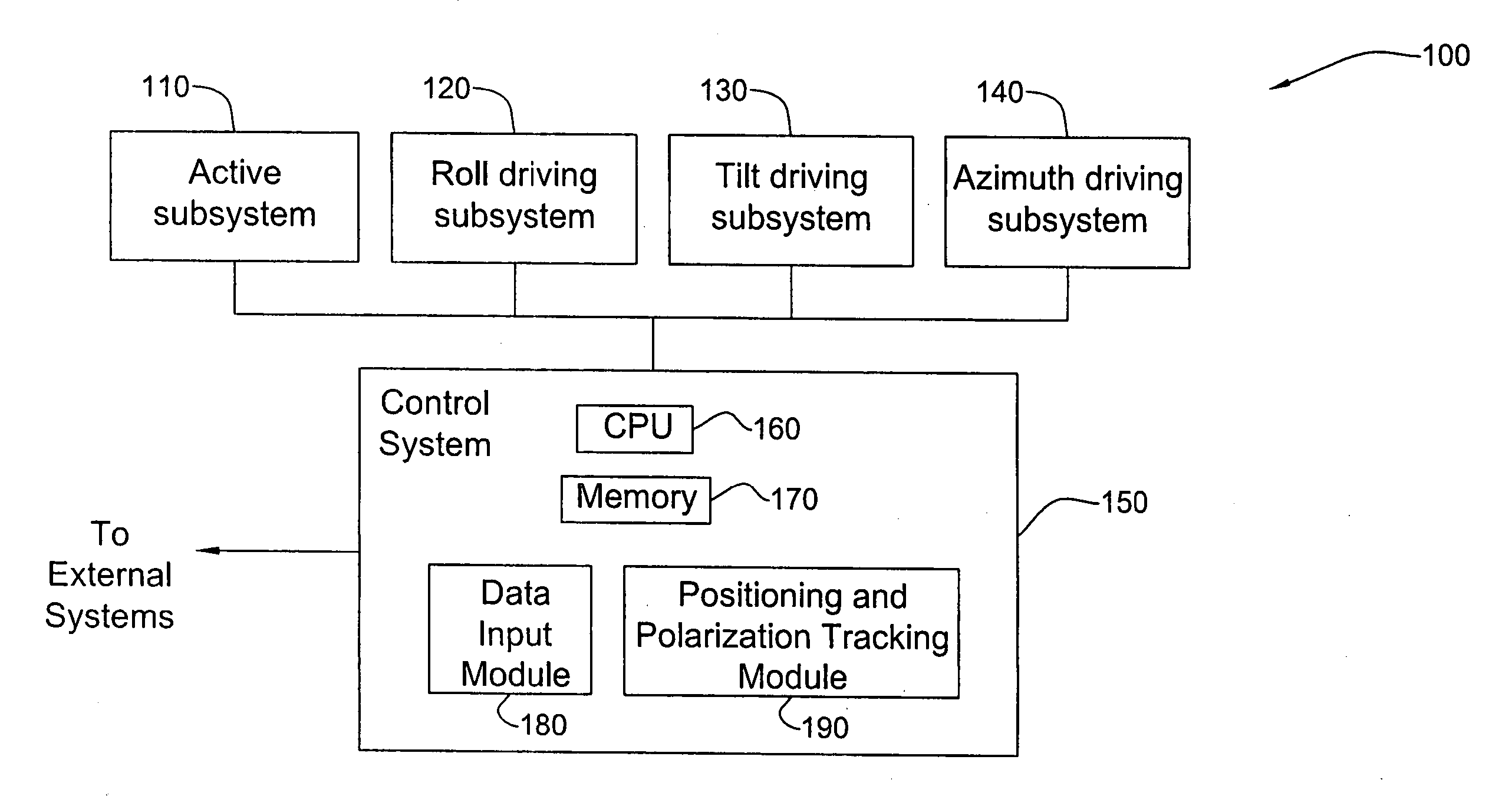
[0046] According to certain embodiments, the present invention provides for a planar antenna and preferably a phased array antenna system to be disposed onto a platform, and preferably a moving platform (e.g. airborne platform) for transmitting and / or receiving RF signal having linear polarization to and from at least one target moving relatively to the platform (e.g. geostationary satellite). The antenna system provides positioning capabilities as well as polarization tracking capabilities, thereby improving communication of RF signal having linear polarization between the platform and a target.

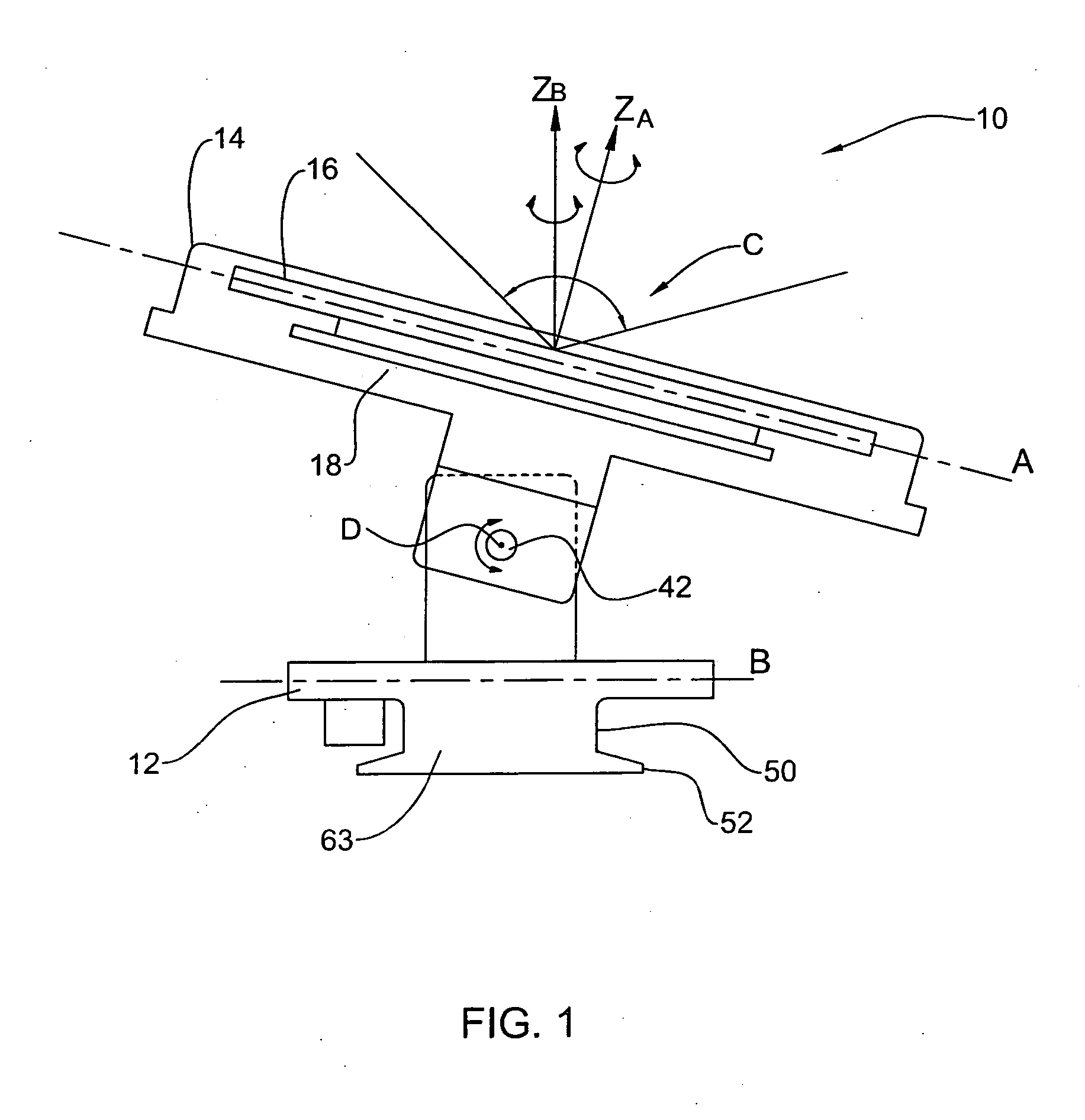
[0047]FIG. 1 is a general side view (in cross section) of an antenna system 10 according to an embodiment of the invention. Antenna system 10 includes, inter-alia, an azimuth driving subsystem 12 defining a horizontal axis B and a ZB axis perpendicular thereto (constituting the central axis of the antenna system). Antenna system 10 further includes a tilt driving subsystem 14 defining an ax...


PUM


Abstract

A phased array antenna system accommodating onto a platform for tracking a target moving relatively to the platform, the antenna system comprising a first planar active subsystem operable for receiving/transmitting an RF signal of a certain linear polarization direction and for selectively performing electronic scanning; a second, roll subsystem coupled to the active subsystem and operable for rotational movement of the active subsystem about a first axis perpendicular to a plane defined by the planar active subsystem; a third, elevation subsystem coupled to the second, roll subsystem and to a fourth azimuth subsystem, the azimuth subsystem defining a central axis of the antenna system and being operable for providing rotational movement of the first planar subsystem about the central axis, the elevation subsystem being configured to provide a certain angular orientation between the plane defined by the active subsystem and a plane defined by the azimuth subsystem, thereby allowing positioning the first planar active subsystem with respect to the target such that the linear polarization direction is substantially aligned with a linear polarization direction of RF radiation received and/or transmitted by the target.

Description

FIELD OF THE INVENTION [0001] This invention relates to phased array antennas and planar antennas and more specifically to phased array antennas of the kind suitable to be mounted onto moving platforms e.g. aircrafts, ships, cars etc., used for satellite communication, or for tracking moving targets. BACKGROUND OF THE INVENTION [0002] Nowadays, many moving platforms (e.g. aircrafts, ships, cars, etc.) are required to have satellite communication capabilities. One exemplary requirement relates to an entertainment system for offering passengers with e.g. internet access, live television broadcast and the like. [0003] During motion, the moving platform (e.g. the aircraft) is engaged in communication with a particular satellite, tracking it across the sky until it disappears over the horizon, and prior to its disappearance establishes communication with another satellite. Therefore, antennas on-board the moving platforms are typically equipped with suitable positioning and tracking syst...

Claims


Application Information

Patent Timeline
IPC IPC(8): H01Q3/00
CPCH01Q1/18H01Q3/04H01Q3/08H01Q3/26H01Q13/10H01Q21/064H01Q1/30H01Q1/28H01Q3/00
Inventor ILUZ, ZEEVSAMSON, CLAUDEGAFNI, AMNON
Owner ELTA SYST LTD
Why Eureka
Try Eureka