
Antenna switching arrangement

a switching arrangement and antenna technology, applied in the field of switching arrangement, can solve the problems of significant communication performance degradation, linear polarization configuration deformation, and reducing the energy available for each closely spaced tag

Active Publication Date: 2011-02-10
RF CONTROLS
View PDF50 Cites 43 Cited by
  • Summary
  • Abstract
  • Description
  • Claims
  • Application Information

AI Technical Summary

Benefits of technology

"The invention provides an antenna switching arrangement and method for improving the communication performance of RFID systems in environments where a large number of RFID tags are present. The arrangement can change the polarization of the antenna array and simultaneously accommodate the phasing and splitting circuits required for communication. This can lead to improved communication performance even when RFID tags are closely spaced or when the reader is at a distance from the tags."

Problems solved by technology

The degradation may be generated by interference from other RFID tags and / or the RFID tags may block or partially block one another along a signal path to the antenna generating the interrogation signal.
However, communications performance is significantly degraded in linear polarization configurations, if the signal / antenna alignment is not optimal.
However, where RFID tags are closely spaced, circular polarisation interrogation signals may experience significant communications performance degradation, thereby reducing the amount of energy available for each of the closely spaced tags, reducing the minimum operating distance between a reader and the plurality of tags and / or requiring increased incident / transmit power from the reader.
It may not always be possible to increase reader transmit power because of radio regulations and decreasing the distance between the reader and the plurality of tags may not be possible because of the use case or physical environment.
Although U.S. Pat. No. 6,367,697 teaches switching and phase delay, it does not disclose or suggest a means to change and / or dynamically switch the polarisation of the antenna array and simultaneously accommodate the phasing and splitting circuits required.

Method used


Image

  • Antenna switching arrangement
  • Antenna switching arrangement
  • Antenna switching arrangement

Examples


Embodiment Construction

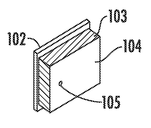
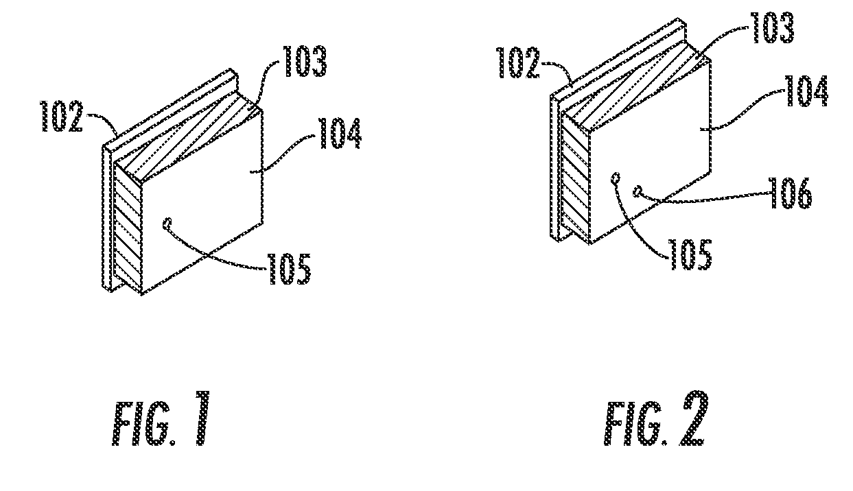
[0025]The inventors have recognized that for a given RFID tag antenna orientation, signal interference level and / or partial signal blockage situation, the reception of a reader signal by and / or the signal strength of any response signal returned from an RFID tag can be significantly impacted by the signal polarization that is applied to the reader signal. Therefore, a reader / antenna with the ability to transmit an reader signal with multiple polarizations may be able to detect RFID tags that would otherwise be missed by a reader / antenna with the traditional single polarization interrogation signal capability.

[0026]A reader / antenna equipped to transmit the reader signal with multiple polarizations may be configured to apply each of these alternative reader signal polarizations in sequence, while monitoring the number of responses and signal strengths of each response obtained from each polarization of the reader signal. By comparing these results, the reader and / or a processor couple...


PUM


Abstract

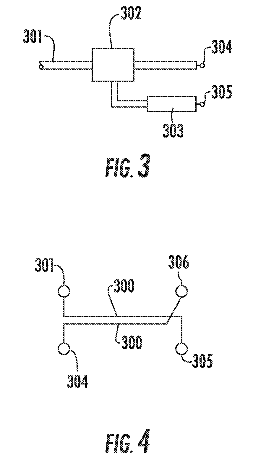
An antenna switching arrangement with a quadrature arrangement of transmission lines through which a desired signal path may be configured via switches selectively grounding junctions of the switching arrangement. The desired path routing a signal from an input port to one or both of first and second output ports to generate a signal with vertical linear polarization, horizontal linear polarization or circular polarization. The selected polarization may be changed as desired and / or multiple antenna switching arrangements applied to enable simultaneous signals with different polarizations.

Description

BACKGROUND[0001]1. Field of the Invention[0002]This invention relates to a switching arrangement for controlling the polarisation of multi-element antenna arrays and more particularly to antenna arrays used in Radio Frequency Identification Systems.[0003]2. Description of Related Art[0004]Radio Frequency Identification (RFID) technology utilizes a tag transponder, which may be associated with / attached to an object, and a reader generating an interrogation signal to read and identify the RFID tag(s) within range of the interrogation signal. RFID technologies are broadly categorized using “active” tags with a local power source enabling longer read ranges and / or the communication of greater amounts of data, and unpowered “passive tags” typically transmitting only a unique RFID tag identifier in response to an interrogation signal.[0005]A typical RFID tag includes an electronic circuit that may be in the form of an integrated circuit or silicon chip, whereby the circuit stores and comm...

Claims


Application Information

Patent Timeline
Patent Type & Authority Applications(United States)
IPC IPC(8): G06K7/02G06K19/06
CPCH01P5/02H01Q21/24H01Q3/24G06K7/01H01Q21/245
Inventor BLOY, GRAHAM P.PIERCE, MATTHEW E.TURNER, CHRISTOPHER GORDON GERVASE
Owner RF CONTROLS
Learn More