Dual antenna capable of transmitting and receiving circularly polarized electromagnetic wave and linearly polarized electromagnetic wave

a technology of circular polarization and electromagnetic waves, applied in the direction of elongated active element feed, resonance antennas, independent non-interacting antenna combinations, etc., can solve the problems of low-noise amplifier circuit saturated with signals and invite interference, and achieve the effect of low noise and high reliability

Inactive Publication Date: 2005-04-12
ALPS ALPINE CO LTD
View PDF9 Cites 43 Cited by
  • Summary
  • Abstract
  • Description
  • Claims
  • Application Information

AI Technical Summary

Benefits of technology

An object of the present invention, attempted in view of this problem with the prior art, is to provide a highly reliable dual antenna made less susceptible to the adverse effect of the electromagnetic wave radiating from its rod-shaped antenna on an adjoining patch antenna.

Problems solved by technology

However, if this undesired signal is a powerful electromagnetic wave for mobile telephony radiating from the adjoining rod-shaped antenna 4, there may arise a problem that the low-noise amplifier circuit is saturated with signals and invite interference.

Method used


Image

  • Dual antenna capable of transmitting and receiving circularly polarized electromagnetic wave and linearly polarized electromagnetic wave
  • Dual antenna capable of transmitting and receiving circularly polarized electromagnetic wave and linearly polarized electromagnetic wave
  • Dual antenna capable of transmitting and receiving circularly polarized electromagnetic wave and linearly polarized electromagnetic wave

Examples


Embodiment Construction

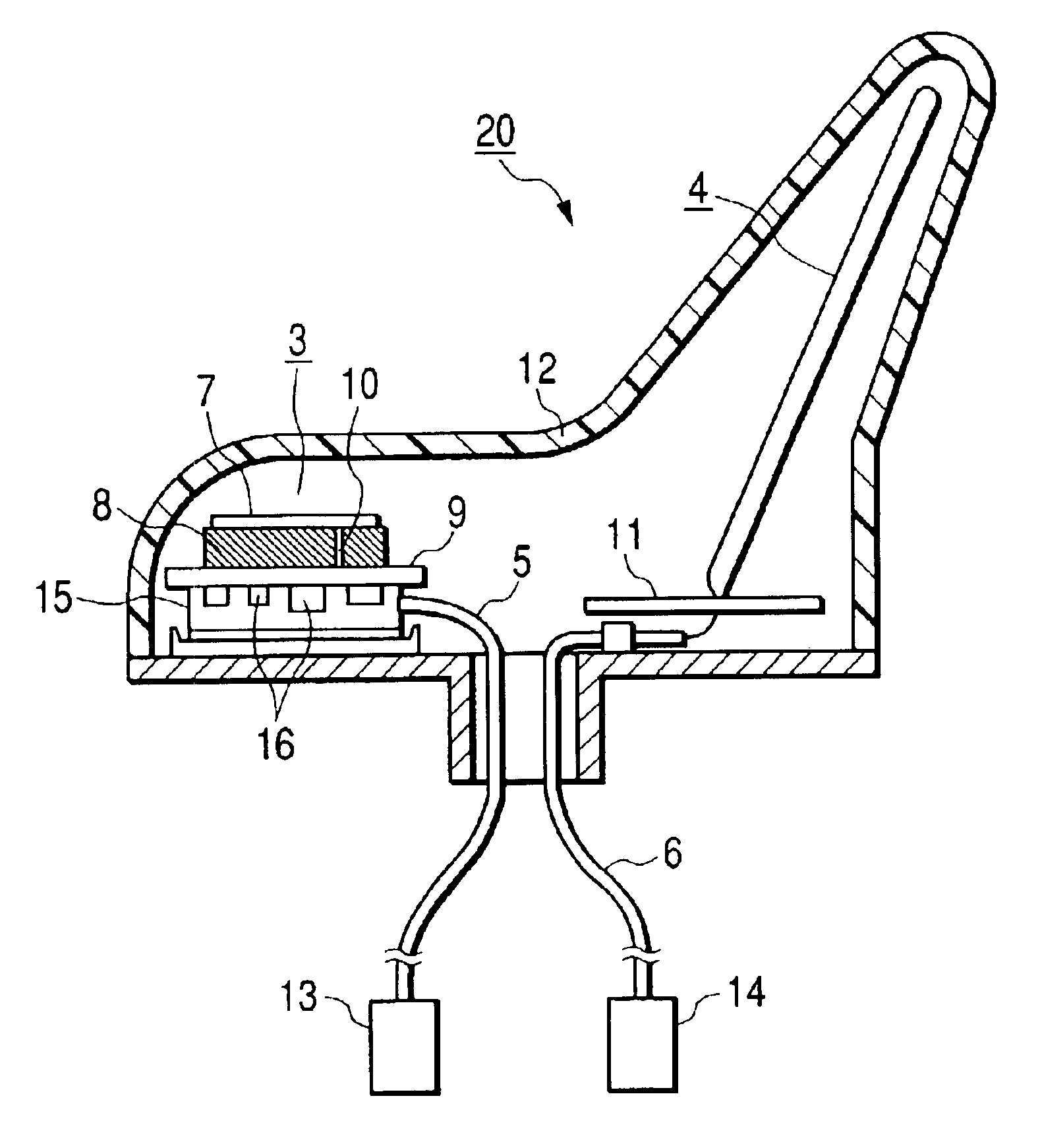
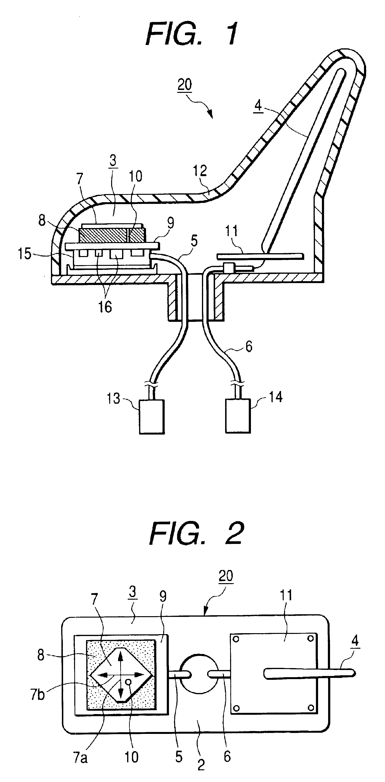
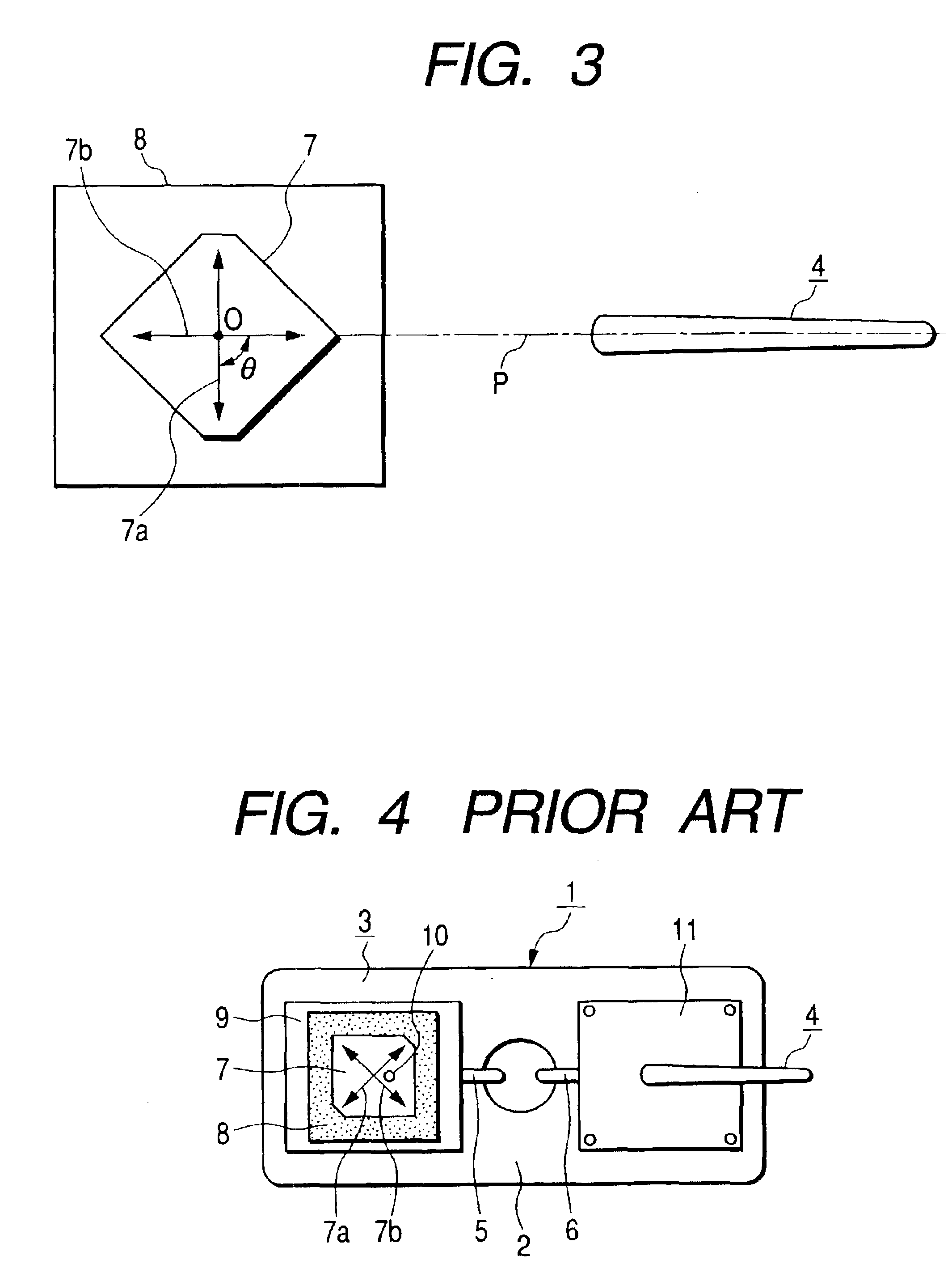
To describe a preferred embodiment of the present invention with reference to accompanying drawings, FIG. 1 shows a schematic section of a dual antenna, which is the preferred embodiment of the invention; FIG. 2, a plan of the dual antenna, in which the illustration of its radome is dispensed with; and FIG. 3, a drawing for describing the positional relationship between the patch antenna and the rod-shaped antenna in the dual antenna. Elements having counterparts in FIG. 4 are denoted by respectively the same reference signs.

A dual antenna 20 shown in FIGS. 1 and 2 is a vehicle-mountable compact antenna unit which has, over a base plate 2, a patch antenna 3 for receiving a circularly polarized electromagnetic wave from a GPS satellite, a rod-shaped antenna 4 for transmitting and receiving a linearly polarized electromagnetic wave for mobile telephony, the two antennas 3 and 4 being disposed in parallel and housed in a common radome 12. The patch antenna 3 is supplied with power via ...


PUM


Abstract

A direction of a power feed patch relative to a rod-shaped antenna is set so that a short axis thereof substantially orthogonally crosses a plane containing an intersection between the short axis and a long axis of the power feed patch of a patch antenna and an axis of the rod-shaped antenna. As a plane of polarization of a linearly polarized electromagnetic wave radiated from the rod-shaped antenna is thereby caused to substantially coincide with a direction of the long axis of the power feed patch and to substantially orthogonally cross a direction of the short axis, even if a powerful wave of a higher frequency than a desired frequency to be received by the patch antenna and difficult to be removed by a band pass filter of a low-noise amplifier circuit is radiated from the rod-shaped antenna, field components of the high frequency electromagnetic wave in the direction of the short axis will become virtually zero.

Description

This application claims the benefit of priority to Japanese Patent Application 2002-114974, filed on Apr. 17, 2002.BACKGROUND OF THE INVENTION1. Field of the InventionThe present invention relates to a dual antenna unitized by installing in parallel a patch antenna capable of transmitting and receiving a circularly polarized electromagnetic wave to and from a Global Positioning System (GPS) satellite or the like and a rod-shaped antenna capable of transmitting and receiving a linearly polarized electromagnetic wave for use in mobile telephony or the like.2. Description of the Related ArtVehicle-mountable patch antennas have been known since years ago as means for finding one's current geographical position by receiving an electromagnetic wave from a GPS satellite, and more recently vehicle-mountable dual antennas, each combining a rod-shaped antenna for mobile telephone use with a patch antenna for GPS use, have become available for practical use. Such a dual antenna has a common ra...

Claims


Application Information

Patent Timeline
Patent Type & Authority Patents(United States)
IPC IPC(8): H01Q5/00H01Q1/12H01Q9/04H01Q21/28H01Q21/00H01Q1/32H01Q1/22H01Q9/32H01Q13/08
CPCH01Q1/12H01Q21/28H01Q9/0428H01Q1/3275
Inventor YUANZHU, DOU
Owner ALPS ALPINE CO LTD
Why Eureka
Try Eureka