Position detecting apparatus and method of correcting data therein

a technology of position detecting and data correction, which is applied in the direction of distance measurement, image enhancement, instruments, etc., can solve the problems of inability to accurately calculate the parallax corrective value, the inability to accurately measure distance z based on parallax, and the cost is much undesired

Inactive Publication Date: 2006-06-01
ARRIVER SOFTWARE AB
View PDF26 Cites 34 Cited by
  • Summary
  • Abstract
  • Description
  • Claims
  • Application Information

AI Technical Summary

Benefits of technology

[0009] It is a general object of the present invention to provide a position detecting apparatus and a method of correcting data in the position detecting apparatus, which is capable of obtaining a corrective value for correcting an erro...

Problems solved by technology

Thus, the distance Z cannot be accurately measured based on the parallax.
However, an adjustment apparatus is required for adjusting the optical axes, and it may cost much undesirably.
In the above-mentioned method of calculating th...

Method used


Image

  • Position detecting apparatus and method of correcting data therein
  • Position detecting apparatus and method of correcting data therein
  • Position detecting apparatus and method of correcting data therein

Examples


Embodiment Construction

[0024] A position detecting apparatus and a method of correcting data in the position detecting apparatus according to preferred embodiments of the present invention will be described below with reference to the accompanying drawings.

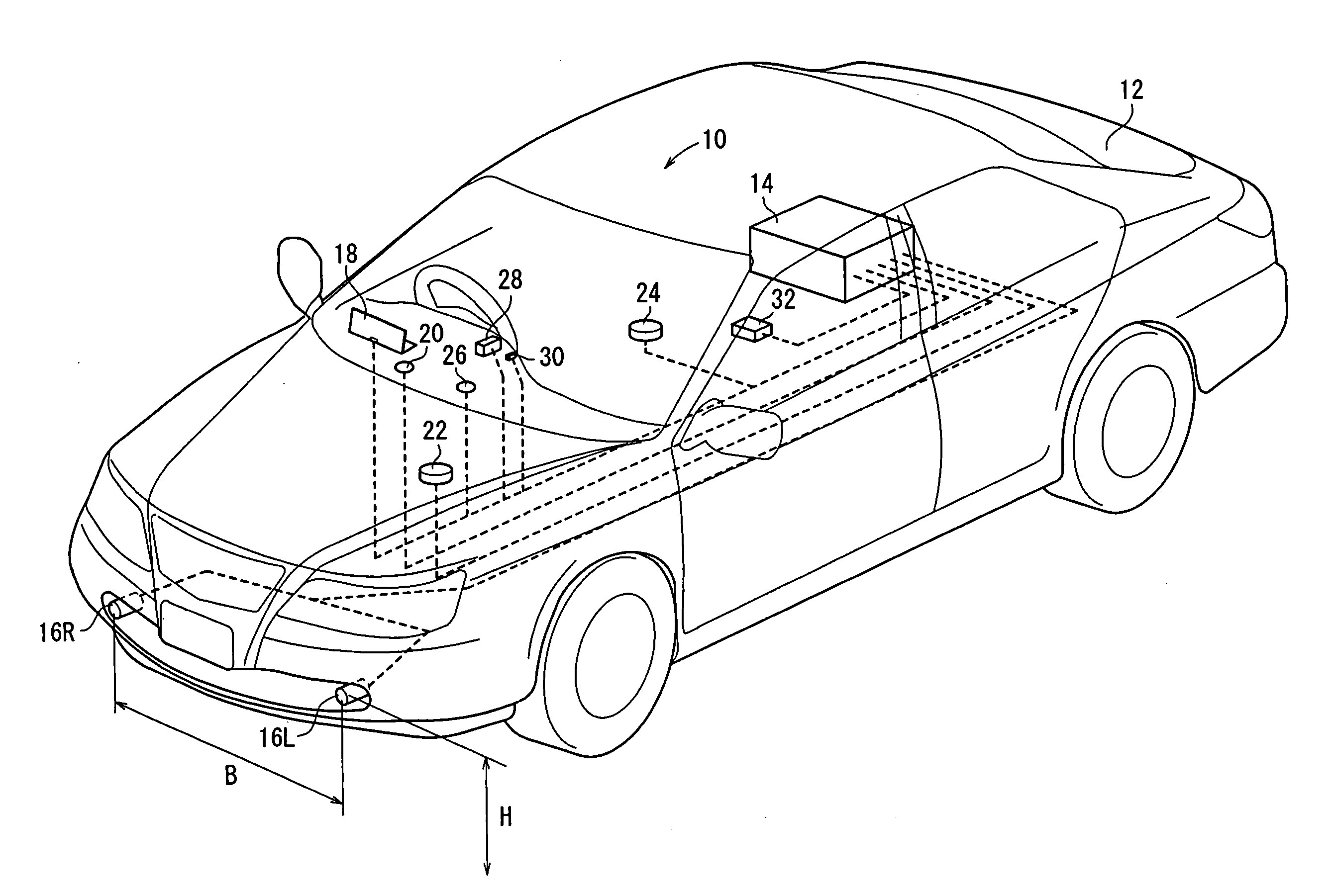
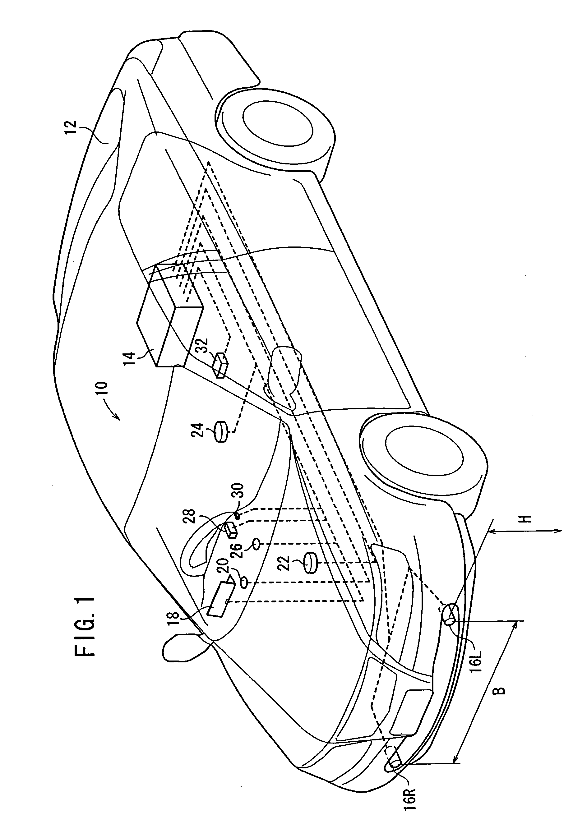
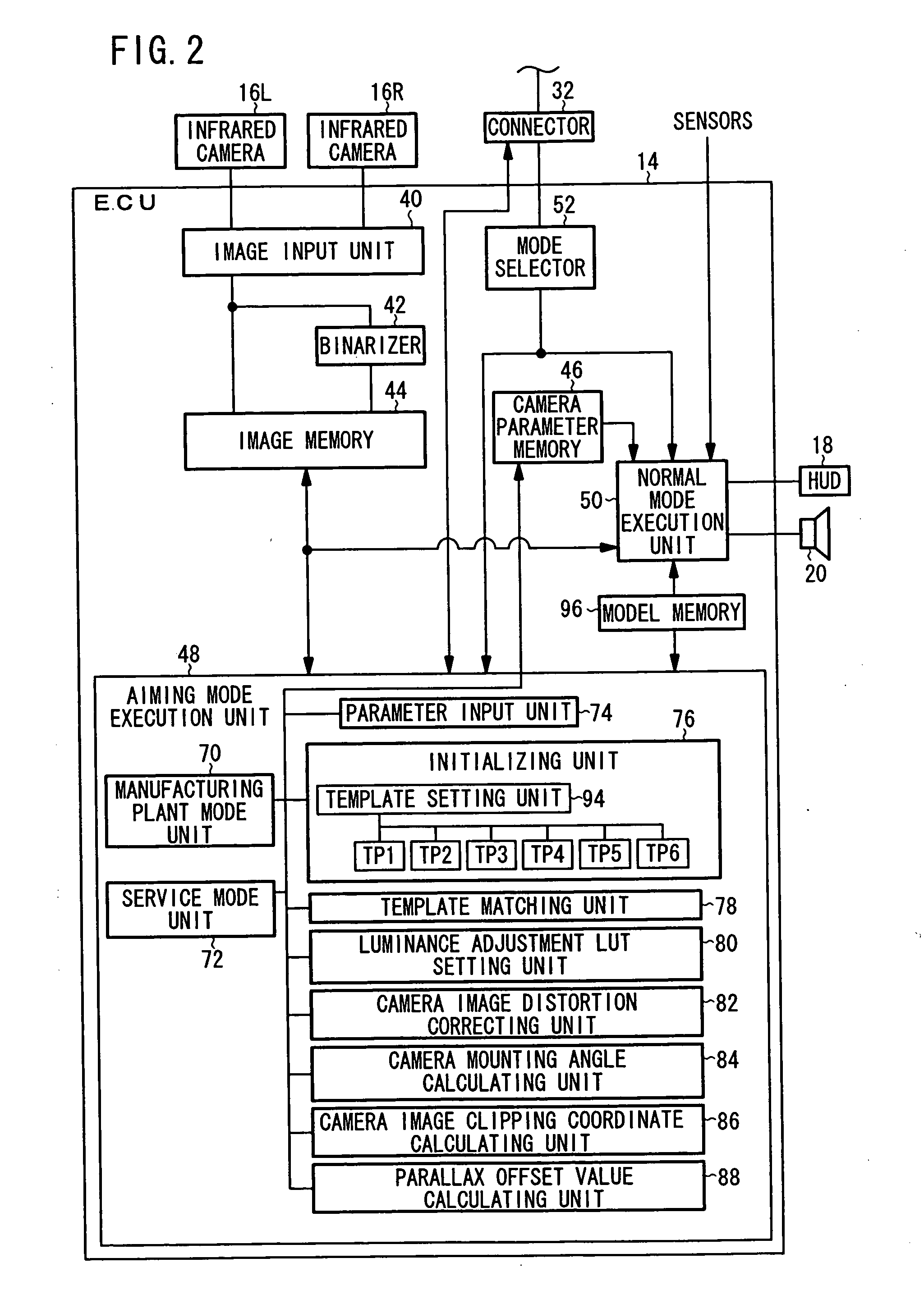
[0025] As shown in FIG. 1, a night vision system (vehicle vicinity monitoring apparatus) 10 according to an embodiment of the present invention is installed on a vehicle 12. The night vision system 10 has an ECU (Electronic Control Unit) 14 serving as a main controller, a pair of left and right infrared cameras (a first imaging unit, a second imaging unit) 16R, 16L, an HUD (Head-Up Display) 18 for displaying a detected image, a speaker 20 for outputting an alarm sound, a speed sensor 22 for detecting a running speed, a yaw rate sensor 24 for detecting a yaw rate of the vehicle 12 when the vehicle 12 is driven, a solar radiation sensor 26, a headlight switch 28, a main switch 30 for selectively activating and inactivating the night vision system 10, and...


PUM


Abstract

Two aiming targets are arranged at positions that are away from two infrared cameras by a predetermined distance. One of the infrared cameras images one of the aiming targets, and the other of the infrared cameras images the other of the aiming targets. Assuming that the obtained images relate to an image of one aiming target, a parallax offset value is calculated. The correction of position is performed based on the parallax offset value.

Description

BACKGROUND OF THE INVENTION [0001] 1. Field of the Invention [0002] The present invention relates to a position detecting apparatus which obtains images of one object with a plurality of imaging units for detecting the position in an actual space of the object, and a method of correcting data in the position detecting apparatus. [0003] 2. Description of the Related Art [0004] There has been developed a vehicle vicinity monitoring apparatus for obtaining images of one object with two imaging units mounted on a vehicle, for example, either measuring the distance up to the object based on the parallax between the obtained images, or measuring the position in an actual space of the object with respect to the vehicle, and informing the driver of whether there is an obstacle ahead of the vehicle or not (see Japanese Laid-Open Patent Publication No. 2003-216937). [0005] In this invention, a distance Z from the imaging units to the object can be calculated by an equation (1) below using an ...

Claims


Application Information

Patent Timeline
IPC IPC(8): H04N7/18B60R21/00G01C3/00G01C3/06G06T1/00
CPCG06T7/002G06T7/0042G06T7/0075G06T2207/10012G06T2207/10048G06T2207/30261G06T7/593G06T7/73G06T7/85
Inventor NAGAOKA, NOBUHARUSAKA, MASAKAZUWATANABE, MASAHITO
Owner ARRIVER SOFTWARE AB
Why Eureka
Try Eureka