High-gain diode-pumped laser amplifier

a laser amplifier and diode pump technology, applied in laser optical devices, laser details, active medium shape and construction, etc., can solve the problems of degrading the output beam quality of lasers, affecting the efficiency of side-pumped dpssl designs, and limiting the design of end-pumped lasers to generating relatively low average output power levels. , to achieve the effect of minimizing parasitic amplified spontaneous emission

Inactive Publication Date: 2006-06-01
MANNI JEFFREY G
View PDF17 Cites 65 Cited by
  • Summary
  • Abstract
  • Description
  • Claims
  • Application Information

AI Technical Summary

Benefits of technology

[0022] The disclosed apparatus and method utilize a laser active slab with a source of pump power to amplify an input laser beam, where the laser active slab includes a block of laser active material having opposed lateral faces defining a wedge lateral dihedral angle, opposed longitudinal faces, and opposed parallel transverse faces. The wedge lateral dihedral angle may be selected so as to minimize parasitic amplified spontaneous emission in the laser active slab. The lateral faces may include optical coatings highly transmitting at a wavelength of the pump power and highly reflecting at a lasing wavelength. The source of pump power may be one or more laser diode bars and microlenses producing a gain sheet in the laser active slab. The apparatus may include one or more external mirrors highly reflecting at the lasing wavelength positioned and oriented to provide additional zig-zag passes through the gain sheet for the input laser beam and thereby providing multi-pass laser amplifiers.

Problems solved by technology

End-pumped lasers designs are generally regarded as being limited to generating relatively low average output power levels, due to the possibility of thermal fracture of the solid-state laser medium when diode pump power is increased beyond a specified level.
End-pumped DPSSL designs that allow pump light to penetrate deeply into the solid-state medium, and that distribute pump power more uniformly along the entire length of a laser rod or slab, are exceptions, but these lasers often suffer from degraded output beam quality unless certain preventive design measures are implemented.
Historically, side-pumped DPSSL designs have been somewhat less efficient, and have exhibited poorer beam quality, than end-pumped lasers.
These requirements significantly complicate the design and fabrication of such laser active slab designs.
However, using the design taught by Baer '031 presents a challenge in both initially achieving and maintaining the tightly-folded beam alignment with the diode emitters.
This complicates practical applications of the Baer '031 design, especially when applied to a moderate- or high-volume production setting.
Moreover, unwanted amplified spontaneous emission (ASE), or parasitic oscillation, generated at the lasing wavelength of the laser active medium can build up in the laser active slab between the parallel high-reflection lateral surfaces.
Such micro-patterned coatings are difficult and expensive to fabricate, and may not be considered practical for production in moderate or high volume applications.
This is because the reflecting surfaces would no longer be parallel, and the apex points of the zig-zag path would therefore be spaced non-uniformly along the length of the laser active slab.
However, it has been demonstrated that the 0.6 milliradian lateral wedge angle cited in Baer '031 is not adequate to suppress lateral parasitics and ASE when pumping Nd-doped 1064-nm laser slabs with high power levels of 40 W or more.
Furthermore, the multiple-pass optical path is quite complicated due to the requirement to match the reflection points to the active areas of the laser diode”.
Furthermore, this and other gain module designs in which the amplified beam enters and exits the laser active slab at the end faces are difficult to multiple-pass without using a Faraday rotator.
'489 can be difficult and expensive to fabricate, especially if the end mirrors used for creating the zig-zag beam path are coated directly onto the slab end faces.
It does not appear that prior art devices employing thin-film coatings to establish a zig-zag beam path have successfully dealt with the problem of unwanted parasitics and ASE.
Furthermore, achieving three or four zig-zag passes in such thin-film-coated slabs has often not been possible or practical.

Method used


Image

  • High-gain diode-pumped laser amplifier
  • High-gain diode-pumped laser amplifier
  • High-gain diode-pumped laser amplifier

Examples


Embodiment Construction

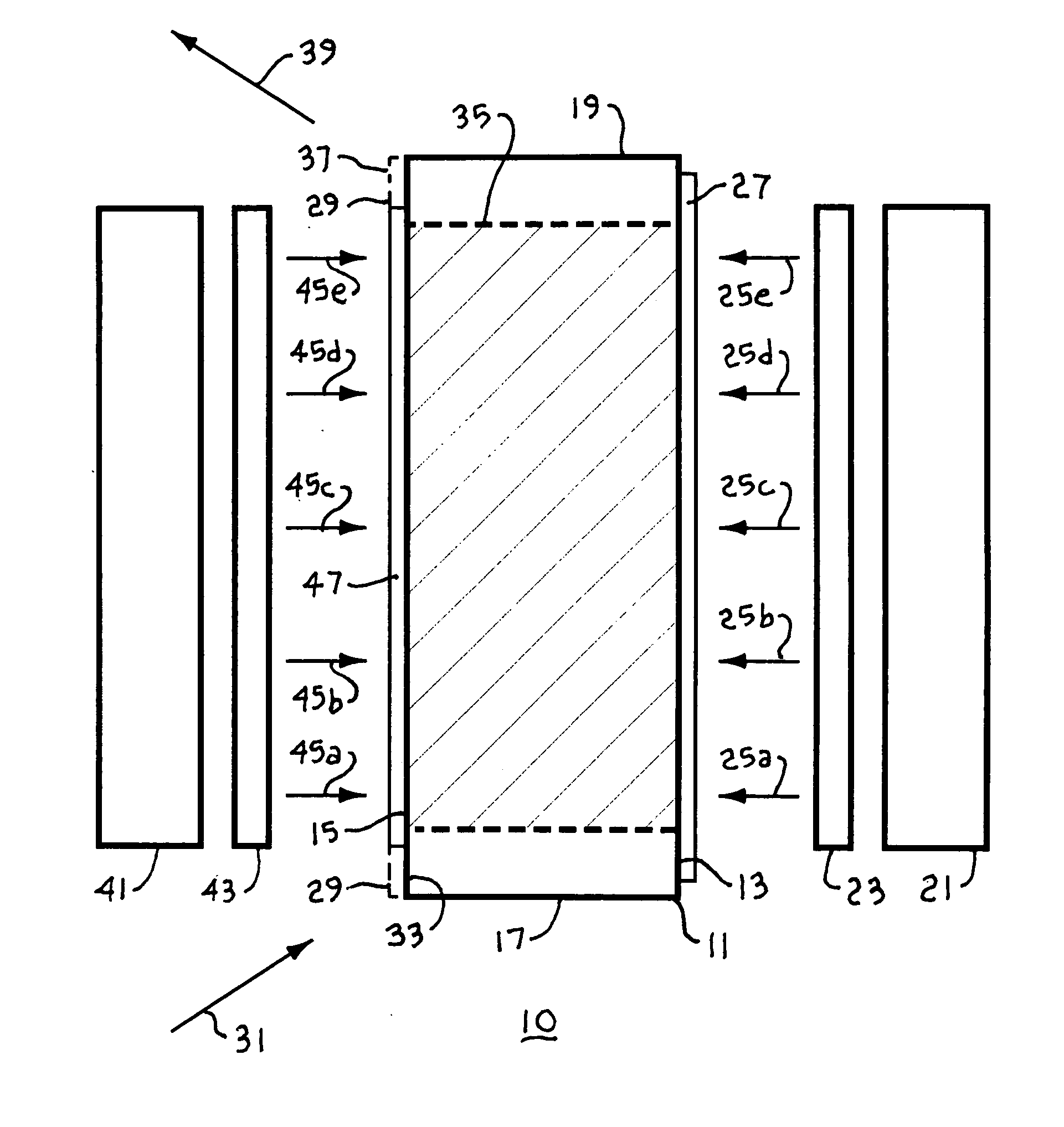
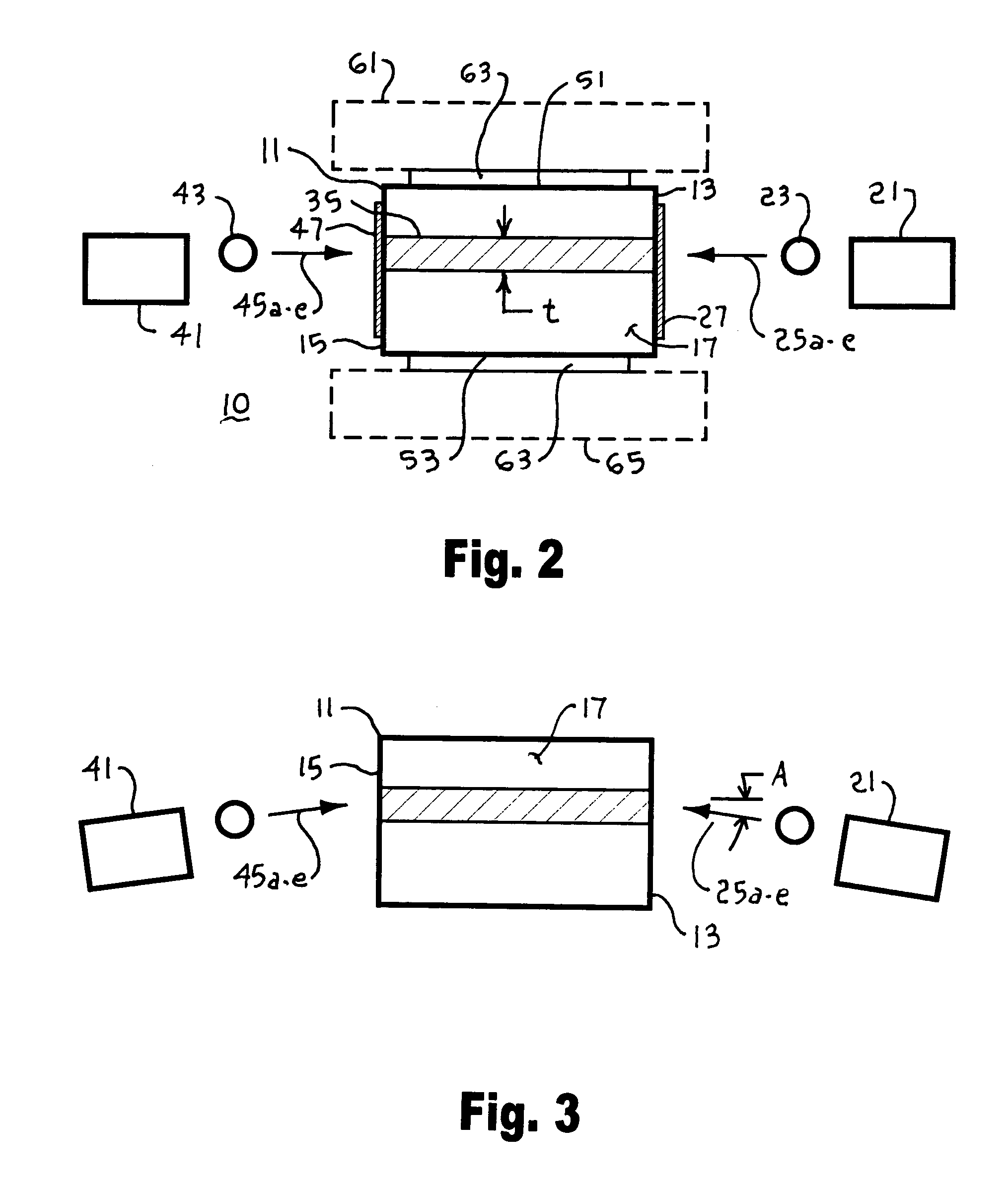
[0061] There is shown in FIGS. 1 and 2 simplified diagrammatical illustrations of a laser amplifier 10 for an incoming laser beam 31 having a specified lasing wavelength, the laser amplifier 10 including a laser active slab 11, a diode bar 21, and an optional microlens 23. The laser active slab 11 includes a first lateral face 13, a second lateral face 15 opposed to the first lateral face 13, a first longitudinal face 17, and a second longitudinal face 19 opposed to the first longitudinal face 17. The laser active slab 11 may comprise a block of laser active material such as: Nd:YAG, Nd:YLF, Nd:YVO4, Nd:GdVO4, Yb:YAG, Yb:YLF, Tm:YAG, Tm:YLF, and Tm:YAlO.

[0062] The diode bar 21 comprises a plurality of semiconductor diode lasers (not shown), operating at a pump power wavelength and emitting a respective plurality of radiation beams, as represented by diode emitter beamlets 25a-25e. The laser active slab 11 may include an optical coating 27, such as a thin-film dichroic coating, disp...


PUM


Abstract

A laser amplifier includes a laser active slab with a source of pump power to amplify an input laser beam, the laser active slab including a block of laser active material having opposed lateral faces defining a wedge lateral dihedral angle, opposed longitudinal faces, and opposed parallel transverse faces, the wedge lateral dihedral angle specified to minimize parasitic amplified spontaneous emission. The source of pump power may be one or more laser diode bars and microlenses producing a gain sheet in the laser active slab. The lateral faces may include optical coatings highly transmitting at a wavelength of the pump power and highly reflecting at a lasing wavelength to provide a folded path for the input laser beam though the gain sheet. The laser amplifier may optionally include one or more external mirrors highly reflecting at the lasing wavelength positioned and oriented to provide one or more additional zig-zag passes through the gain sheet for the input laser beam and to provide a multi-pass-amplified laser beam.

Description

BACKGROUND OF THE INVENTION [0001] 1. Field of Invention [0002] The present invention relates to solid state laser amplifiers pumped by semiconductor laser diodes and, in particular, to a laser amplifier operating using a wedge configured laser active slab to reduce the generation of amplified spontaneous emission within the laser amplifier. [0003] 2. Description of the Background Art [0004] It is known in the relevant art to use laser emission from one or more semiconductor diode lasers to pump a solid-state laser medium (i.e., diode pumping). Diode pumping provides for high power solid-state laser devices that are more efficient, more compact, more reliable, and that have better beam quality, than lamp-pumped solid-state lasers of comparable output power. Many new diode-pumped solid-state laser (DPSSL) designs have emerged in recent years due to an increasing array of new solid-state laser materials, and a wider range of diode laser pump wavelengths from which the laser designer c...

Claims


Application Information

Patent Timeline
Patent Type & Authority Applications(United States)
IPC IPC(8): H01S3/091
CPCH01S3/083H01S3/0941H01S3/1611H01S3/1643H01S3/2325H01S3/2333H01S3/2341H01S2301/02H01S3/005H01S3/0405H01S3/042H01S3/0606H01S3/0615H01S3/0625H01S3/063H01S3/08095H01S3/08077
Inventor MANNI, JEFFREY G.
Owner MANNI JEFFREY G
Why Eureka
Try Eureka