Radio communication terminal and handoff control method

Inactive Publication Date: 2006-06-01
KYOCERA CORP
View PDF8 Cites 5 Cited by
  • Summary
  • Abstract
  • Description
  • Claims
  • Application Information

AI Technical Summary

Benefits of technology

[0028] According to the radio communication terminal and the handoff control method, when the radio communication terminal performs a handoff to the other b

Problems solved by technology

In this event, because the radio communication terminal that is receiving the BCMCS performs the handoff, it is possible that this precious radio resource is wasted.
As a result, the base station must be able to use the channel as the precious radio resource because there is no other radio communication terminal, which wishes to receive the service information, except this radio communication terminal in the service area of such base station as the destination of handoff, nevertheless the base station must start the broadcast of the service information at t

Method used


Image

  • Radio communication terminal and handoff control method
  • Radio communication terminal and handoff control method
  • Radio communication terminal and handoff control method

Examples


first embodiment

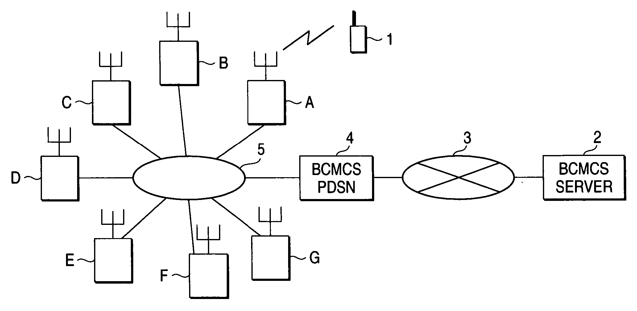
[0063] Assumed that the base stations A to D now broadcast the BCMCS service information but the base stations E to G do not broadcast the BCMCS service information. At this time, as shown in FIG. 8, the radio communication terminal 1 is located within the cell that the base station A covers, and receives the service information broadcasted from the base station A. The user moves toward the base station B (in the direction indicated with an arrow) while holding the radio communication terminal 1 in his or her hand (S100). In this case, the radio communication terminal 1 goes across a cell edge of the base station G located adjacent to the base stations A and B before the radio communication terminal 1 arrives at the base station B. At this time, a field strength R(A) from the base station A decreases, while a field strength R(G) from the base station G increases. Thus, the radio communication terminal 1 compares R(A) with R(G) to decide whether or not the handoff should be made (S10...

second embodiment

[0067] A handoff control realized by improving further the above control in the first embodiment is executed in a second embodiment. In the second embodiment, not only the wasteful use of the radio resource can be prevented but also QoS (Quality of Service) indicating that the receiving service information is not disconnected can be improved.

[0068] Assumed that the base stations A to D now broadcast the BCMCS service information but the base stations E to G do not broadcast the BCMCS service information. At this time, as shown in FIG. 8, the radio communication terminal 1 is located within the cell that the base station A covers, and receives the service information broadcasted from the base station A. The user moves toward the base station B (in the direction indicated with an arrow) while holding the radio communication terminal 1 in his or her hand (S200). In this case, the radio communication terminal 1 goes across the cell edge of the base station G located adjacent to the bas...


PUM


Abstract

A radio communication terminal has a communication section which communicates with a base station, and a control section which controls a handoff between a plurality of base stations. The communication section receives a control information indicating whether or not a neighboring base station broadcasts a service information from the neighboring base station when the radio communication terminal performs a handoff from a first base station to the neighboring base station while the radio communication terminal receives the service information broadcasted from the first base station. The control section controls to perform a handoff from the neighboring base station to the first base station when the control section decides that the neighboring base station does not broadcast the service information based on the control information, after the radio communication terminal performs the handoff from the first base station to the neighboring base station.

Description

CROSS-REFERENCE TO RELATED APPLICATIONS [0001] This application is based upon and claims the benefit of priority from the prior Japanese Patent Applications No. 2004-314588, filed on Oct. 28, 2004, the entire contents of which are incorporated herein by reference. BACKGROUND OF THE INVENTION [0002] 1. Field of the Invention [0003] The present invention relates to a radio communication terminal used in a radio communication system that can deal with a broadcast service and / or a multicast service, and a handoff control method of the radio communication terminal. [0004] 2. Description of the Related Art [0005] In the radio communication system, as the technology to continue a communication while moving among service areas (e.g., cells or sectors) of the base stations, the process of switching the base station, to which the radio communication terminal is to be connected, in response to the signal quality of a communication between the radio communication terminal and the base station (...

Claims


Application Information

Patent Timeline
IPC IPC(8): H04Q7/20H04W4/06H04W36/08H04W36/20
CPCH04W4/06H04W36/0055H04W36/0007H04W36/30H04W36/08
Inventor HIDAKA, HIROYUKI
Owner KYOCERA CORP
Why Eureka
Try Eureka