Manually adjustable clutch assembly with visual indicator

a clutch and visual indicator technology, applied in the field of manual adjustable clutches, can solve the problems of adding weight, difficult to determine the extent of clutch wear, and adding cost to the clutch assembly

Inactive Publication Date: 2006-06-01
EATON INTELLIGENT POWER LTD
View PDF20 Cites 60 Cited by
  • Summary
  • Abstract
  • Description
  • Claims
  • Application Information

AI Technical Summary

Benefits of technology

[0011] An indicator associated with the housing may indicate the extent of wear of the clutch by reference to the axial position of the shaft relative to the indicator. The indicator may be a graphical reference such as a label or placard bearing indicia that is located adjacent to the slot on the housing. The indicator may also comprise a pointer having an anchoring end secured to the housing on one side of the shaft and a distal end opposite the anchoring end. The pointer is engaged by the shaft at an intermediate location and displaced as the shaft moves within the slot. The distal end of the pointer moves to a greater extent than the shaft to provide a magnified indication of the extent of wear of the clutch.

Problems solved by technology

It is difficult to determine the extent of clutch wear without disassembling the clutch with most clutch assemblies.
Automatically adjusting clutches have been developed that do not require manual adjustment by a mechanic, however, automatically adjusting clutches require complicated mechanical linkages that add cost to the clutch assembly.
Automatically adjusting clutches also require additional parts that add weight and may complicate clutch operation.
The adjustment mechanism described in the '164 patent does not provide an externally perceptible visual indication of the extent of clutch wear.

Method used


Image

  • Manually adjustable clutch assembly with visual indicator
  • Manually adjustable clutch assembly with visual indicator
  • Manually adjustable clutch assembly with visual indicator

Examples


Embodiment Construction

)

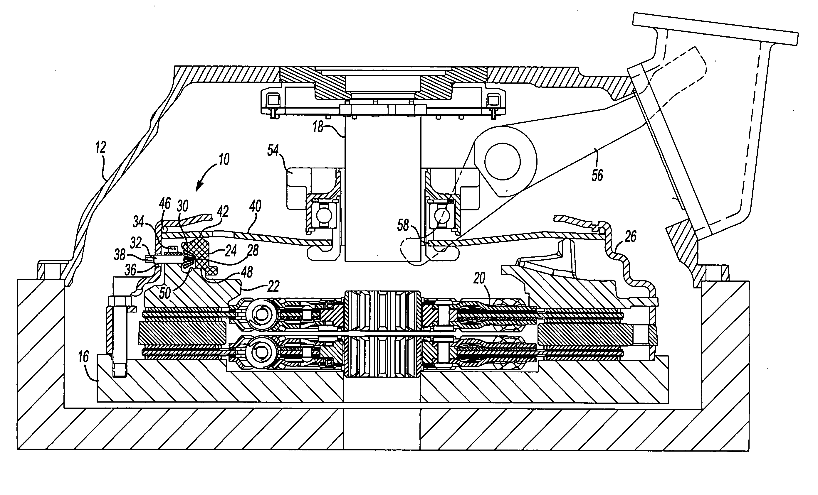
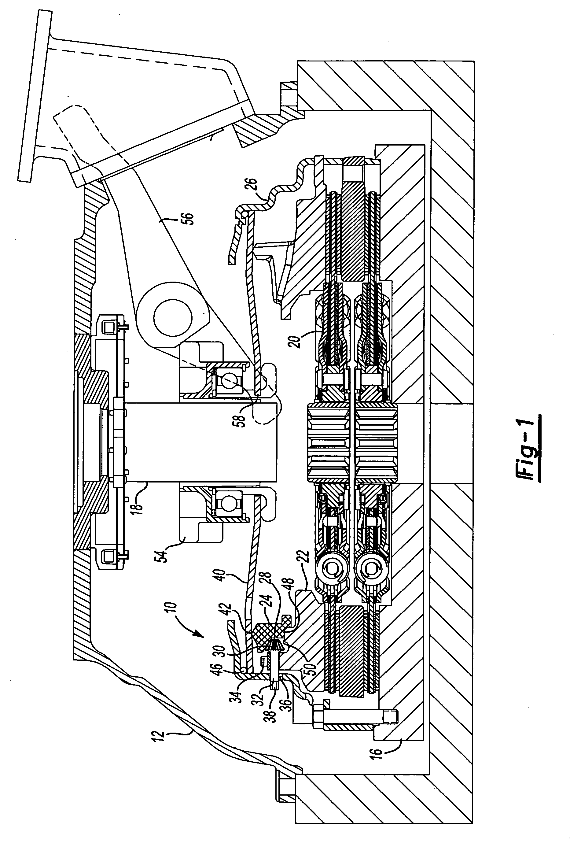
[0028] Referring to FIG. 1, one embodiment of a clutch assembly 10 is shown within a transmission housing 12. The clutch assembly 10 operatively engages the engine flywheel 16. An output shaft 18 for a multi-speed transmission receives torque from the flywheel 16 through the clutch assembly 10. A clutch pack 20 selectively engages the flywheel 16 when pressure is applied by a pressure plate 22. The same reference numerals will be used for similar parts in the several embodiments disclosed.

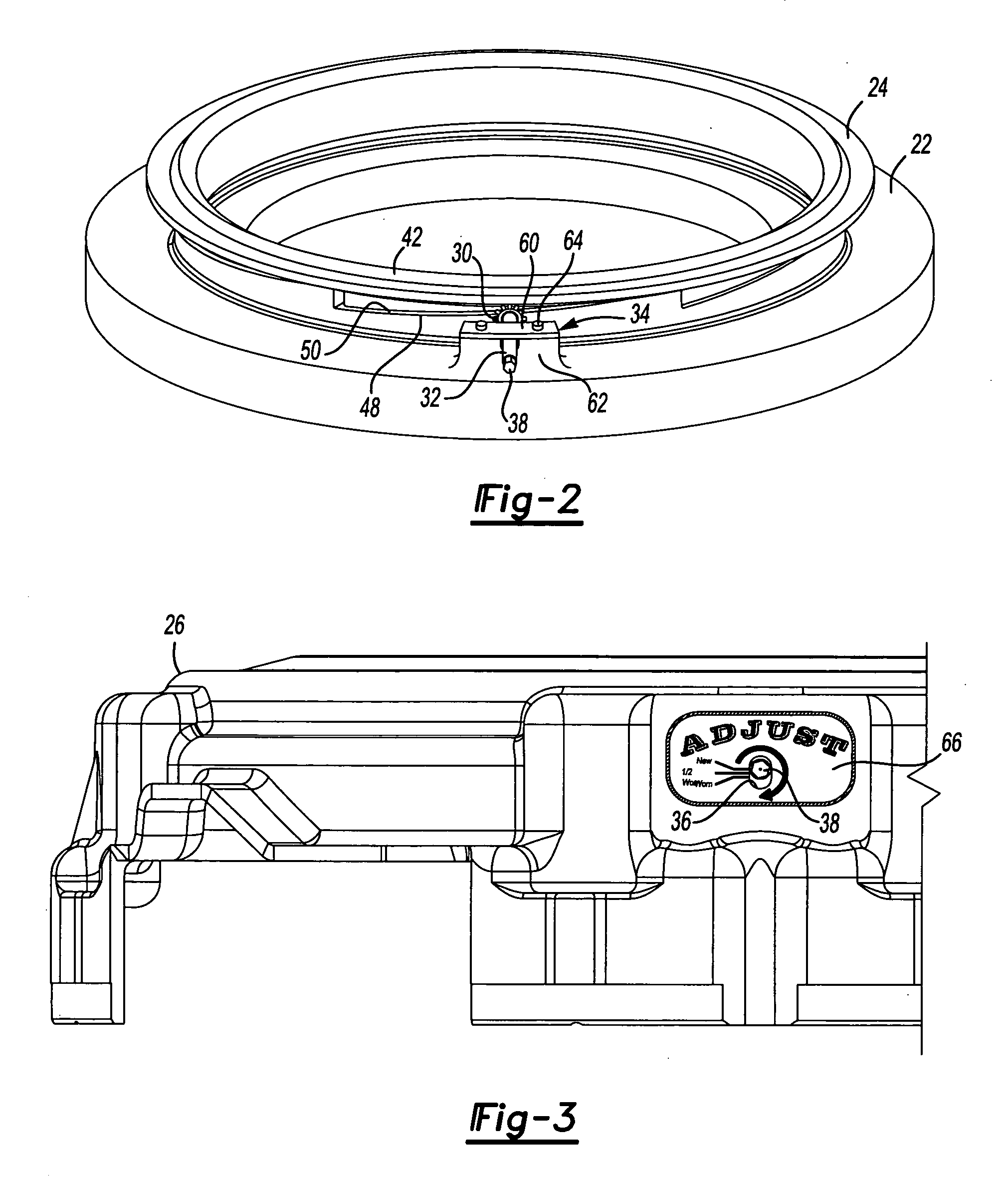
[0029] An adjusting ring 24 is associated with the pressure plate 22. The adjusting ring 24 is rotatably connected to the pressure plate 22 to permit adjustment of the height of the pressure plate. A clutch housing 26 is secured to the flywheel 16 and encloses the clutch pack, pressure plate 22, and adjusting ring 24. The adjusting ring 29 has a plurality of teeth 28. An adjusting gear 30 is provided to engage the teeth 28 of the adjusting ring 24 to rotate the adjusting ring 24 relative to the p...


PUM


Abstract

A manual adjustment mechanism for a clutch is provided wherein an adjusting gear rotates an adjusting ring relative to a pressure plate that are interconnected by means of an inclined surface or a threaded surface. The adjustment gear is mounted on a shaft and is rotated manually. An externally visible indicator is provided that is based upon axial movement of the adjustment gear shaft that moves with the pressure plate and relative to the clutch housing. The adjusting gear and inclined surfaces may be locked in place between service operations by means of locking elements.

Description

BACKGROUND OF THE INVENTION [0001] 1. Field of the Invention [0002] The present invention relates to a manually adjustable clutch that may be adjusted without disassembly of the clutch assembly and that provides an externally visible indication of clutch wear. [0003] 2. Background Art [0004] A clutch interrupts the transmission of torque from an engine to a multiple speed gear transmission. A clutch assembly has a plurality of plates with friction engaging surfaces that transmit torque when the clutch plates are compressed and stop torque transfer when pressure is released from the clutch plates. Clutches are subject to wear over time and require periodic adjustment to assure a desired clutch engagement position and optimal performance. It is difficult to determine the extent of clutch wear without disassembling the clutch with most clutch assemblies. [0005] Automatically adjusting clutches have been developed that do not require manual adjustment by a mechanic, however, automatical...

Claims


Application Information

Patent Timeline
Patent Type & Authority Applications(United States)
IPC IPC(8): F16H47/04
CPCF16D13/757
Inventor MCCUTCHEON, STEVEN E.
Owner EATON INTELLIGENT POWER LTD
Why Eureka
Try Eureka